Camera Angular Calibration
These are a couple of resources that I’ve used for RC camera information that you may find useful,
https://www.chucklohr.com/808/c16/ and https://oscarliang.com/how-to-use-808-16-keychain-camera-manual-and-wiki/. Those links are specific to the 808-16 key chain camera which I have used for bike rides as well as drone flights.
There is mention about field of view measurements in the first link. It references methods used which I was not able to reliably validate. http://www.rcgroups.com/forums/showpost.php?p=22171449&postcount=6843 and https://www.rcgroups.com/forums/showpost.php?p=22446815&postcount=7732 both use the Pythagorean theorem. The camera and background are at fixed points that have a known value of measured distance. In the background are points with known distance values as well. Both of the examples use geometry to solve for the angle. This method would work were it not for lens distortion.
Here is an example of a grid and the barrel distortion created by the wide angle lens.
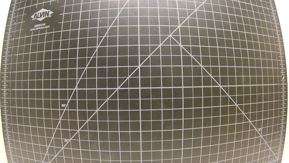
If I were to tally the pixel width of a grid space of 1/2 inch in the center of the example, I get an approximated count of 72 pixels. If I do the same for an edge grid space, that value is now roughly 36 pixels. So the linear properties of the Pythagorean theorem can not be applied.
So I found it easiest to take direct angular measurements using a protractor pattern.
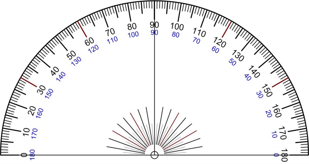
By placing the camera on the pattern and aligning it, I was able to reliably capture the field of view.
It’s fairly simple to get the horizontal field of view, in the example above it is 106 degrees. Now I can do pixel and angle calculations to determine the vertical and angular fields of view. Here are the values I got for my 808-16 camera.
HRes: 1280 pixels
VRes: 720 pixels
HFOV: 108 degrees
VFOV = ( HFOV / HRes ) x VRes
VFOV = ( 108 / 1280 ) x 720
VFOV = 0.084375 x 720
VFOV: 60.75 degrees
ARes^2 = HRes^2 + VRes^2
ARes^2 = 1280^2 + 720^2
2,156,800 = 1,638,400 + 518,400
ARes = √2,156,800
ARes = 1,468.6 pixels
AFOV = ( HFOV / HRes ) x ARes
AFOV = ( 108 / 1280 ) x 1,468.6
AFOV = 0.084375 x 1,468.6
AFOV = 123.91 degrees
In case you missed it, I did ultimately use the Pythagorean theorem to find the angular resolution. Now I’m fairly confident I can measure the angle between 2 points in images. Lets take this photo from one of my flights.
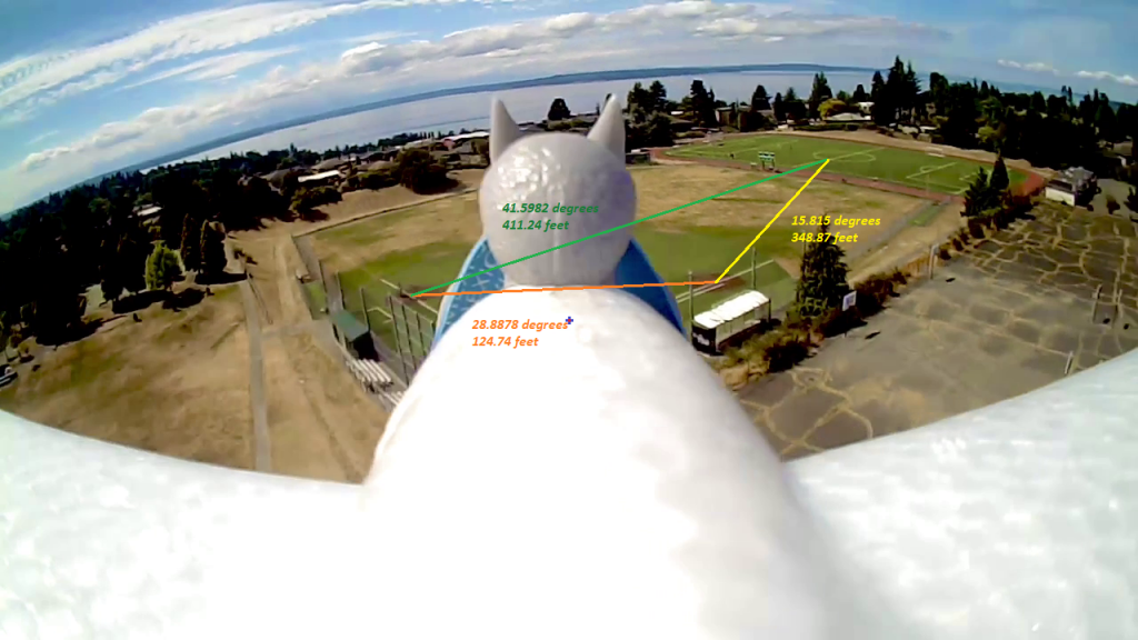
How can I find the distance of objects from the drone?
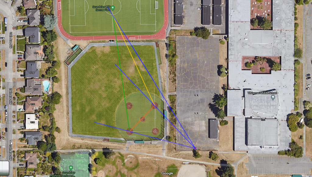
If I measure between 1st and 3rd base, the orange line, I get 342.374 pixels. This converts to 28.8878 degrees using this formula (.084375 x 342.374). The green line is from 3rd base to where the soccer fields center line and south center circle intersect, this comes out to be 41.5982 degrees from 493.0162 pixels. Lastly, the yellow line is from 1st base to the same point on the soccer field, this comes out to be 15.815 degrees from 187.438 pixels.
If I open up Google Maps of the location, https://www.google.com/maps/@47.6968255,-122.380558,225m/data=!3m1!1e3?hl=en, I can measure distances between those points. Those measurements are in the image above.
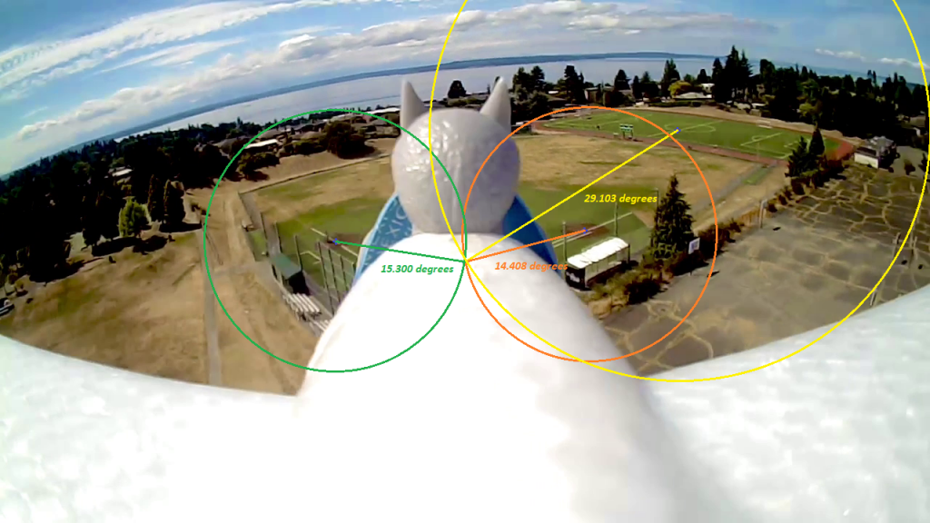
I have marked a center point with a blue cross containing a red center. Here we can determine the angles from center to those points.
1st base = 14.408 degrees
3rd base = 15.300 degrees
soccer field = 29.103 degrees
Using the Pythagorean theorem here still presents a problem, the center point and observed points aren’t on a level plane. Although we can theorize it forms a right angle, we can’t measure distance as we did before because the center point in the photo is on the drone.
Measuring the distance of the drone (camera) to those points also involves some further knowledge, see https://www.scantips.com/lights/subjectdistance.html. In order to use the provided formula, we would need to know specific characteristics of the camera, namely sensor dimension and focal length. Additionally, the field of dimension needs to be at a right angle (perpendicular) to the camera. See http://gsp.humboldt.edu/OLM/Courses/GSP_216_Online/lesson2-2/photogrammetry.html which confirms those observational requirements. The image above is considered and oblique aerial photography, see http://gsp.humboldt.edu/OLM/Courses/GSP_216_Online/lesson2-2/air-photos.html.
Is it still possible to triangulate the position of the drone from the three points?
We’ll need to identify what we know and don’t know. The drone has an unknown elevation, be it above ground or sea level. We don’t know the heading or bearing of the drone. We can observe the horizon. With a horizon, we can determine the pitch of the drone. We can also use the horizon to calculate the angle from horizon for each point.
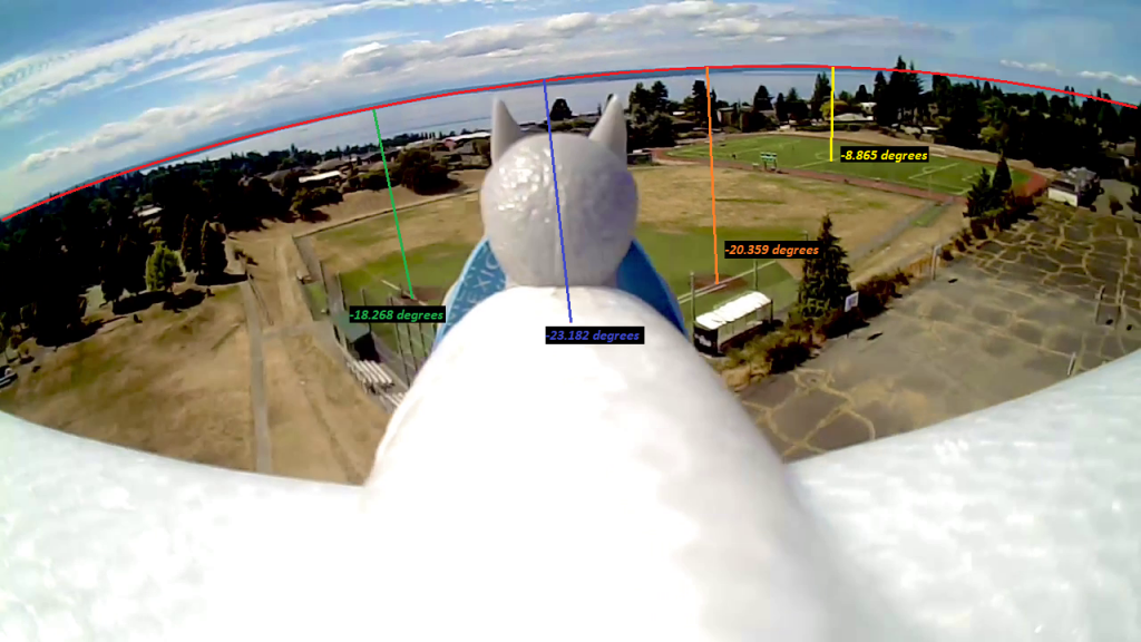
Drone Pitch = -23.182
1st Base = -20.359
3rd Base = -18.268
Soccer Field = -8.865
This gives us some more detail, but the horizontal angle between each of the points is what we can use to pinpoint where the drone is.
The angle between 3rd base and 1st base can be calculated based on the constant of each pixel = .084375 degrees. The image horizon isn’t level, so the Pythagorean theorem will need to be used to determine the pixel distance. The selection between each point shows a rectangle of 374 x 48. Here is the process to determine that angle.
374^2 + 48^2 = c^2
139876 + 2304 = 142180
√142180 = 377.067
377.067 * .084375 = 31.815 degrees
The same process will be used to find the horizontal angle between the soccer field and 1st base. However, the selection rectangle is 140 x 2, so it is level enough to do a pixel to degree calculation.
140 * .084375 = 11.8125 degrees
So all of the horizontal angles are
3rd to 1st = 31.815
1st to soccer = 11.8125
3rd to soccer = 43.6275
Plotting these and overlaying them on the Google map should give us the location of the drone. This can be done in GIMP using layers. First I’ll place the map on a layer. The next layer I’ll draw a horizontal line and be sure its angle is 0 degrees. I’ll continue to add lines on this layer starting at the left point of my first line and draw them based on the angle readings above. The second line will have an angle of 11.8125 degrees and the third line will have an angle of 43.6275 degrees. Now I’ll select the line layer and use the rotate tool to position the converging line point in the general area. I’ll follow this up with moving the selection so the angle lines line up with the points on the map. I’ll go back and forth on the rotate and move tools until it starts to line up on all of the points on the map. One of the points was further away so I drew an extension on the line. Now I have the position of the drone when it took the photo, it’s 47.69610428960238, -122.37881992855307.
I won’t go further with this, but I could find the drone heading and bearing. I can also find the elevation of the drone now that I know the distance of the drone from the map points. The speed of the drone could also be determined since the photos were extracted from a video. I would just need to repeat this process on other frames. The differences on location based on time can give me the results.
Although this process is tedious, automating it with computer vision tools along with parallel processing could provide real-time data with live feeds. The manual steps here just give you a glimpse at how it is possible.