Water Level Monitoring with the ESP32-Cam Module
In this post the ESP32-Cam module will be used to monitor water levels using a HC-SR04 ultrasonic ranging module . The readings will be published to a MQTT broker through the WiFi network. Node-Red will be interfaced with the broker and used to process and display the readings in its WebUI. Node-Red will also operate a pump once thresholds are reached through the broker. Video from the ESP32-Cam will be gathered by Node-Red and included in its WebUI.
This project was created to deal with rain water flooding in a warehouse. Flooding had occurred after hours and went unnoticed causing equipment damage and a time consuming effort of clean up. The intent is to automatically run a pump to remove pooling water and notify staff. In addition, the operational health of the system is monitored and alerts staff if trouble occurs.
Here is the Arduino IDE code for the ESP32-Cam module. It enables the following features on the ESP32-Cam module:
- OV2640 onboard camera
- WiFi networking client
- Webserver, used to stream camera video
- MQTT client, can publish and subscribe to a broker
- HC-SR04 interface using GPIO pins 1 and 3
- Readings are taken every 5 seconds
/* See these links for more details  */
/* https://node-red.blogspot.com/2017/12/how-to-display-led-in-node-red-dashboard.html  */
/* https://fontawesomeicons.com/  */
/* https://randomnerdtutorials.com/esp32-cam-ov2640-camera-settings/  */
/* https://nerdytechy.com/guide-for-arduino-ultrasonic-sensor-hc-sr04/  */
/* https://www.elec-cafe.com/esp32-cam-blynk-ultrasonic-sensor-hc-sr04-with-line-notify/  */


// Declarations and Variables

#include "src/OV2640.h"
#include <WiFi.h>
#include <WebServer.h>
#include <WiFiClient.h>
#include <PubSubClient.h>

#define ENABLE_WEBSERVER

#define CAMERA_MODEL_AI_THINKER

#include "camera_pins.h"  // Include in subfolder of code

OV2640 cam;

const char* mqtt_server = "<IP_Address_of_Broker>";     // Put your MQTT Broker here
const char* ssid =     "<WiFi_SSID>";               // Put your SSID here
const char* password = "<WiFi_Password>";           // Put your PASSWORD here

WiFiClient espClient;
PubSubClient client(espClient);
long lastMsg = 0;
char msg[50];
int value = 0;
int up = 1;

// Data Pins for Ultrasonic sensor
const int TRIG_PIN = 3;        //GPIO 3 = U0RXD
const int ECHO_PIN = 1;        //GPIO 1 = U0TXD

// establish variables for duration of the ping, and the distance result
// in inches and centimeters:
long duration, cm;

// Web Server Function

#ifdef ENABLE_WEBSERVER

WebServer server(80);

void handle_jpg_stream(void)
{
    WiFiClient client = server.client();
    String response = "HTTP/1.1 200 OK\r\n";
    response += "Content-Type: multipart/x-mixed-replace; boundary=frame\r\n\r\n";
    server.sendContent(response);

    while (1)
    {
        cam.run();
        if (!client.connected())
            break;
        response = "--frame\r\n";
        response += "Content-Type: image/jpeg\r\n\r\n";
        server.sendContent(response);

        client.write((char *)cam.getfb(), cam.getSize());
        server.sendContent("\r\n");
        if (!client.connected())
            break;
    }
}

void handle_jpg(void)
{
    WiFiClient client = server.client();

    cam.run();
    if (!client.connected())
    {
        return;
    }
    String response = "HTTP/1.1 200 OK\r\n";
    response += "Content-disposition: inline; filename=capture.jpg\r\n";
    response += "Content-type: image/jpeg\r\n\r\n";
    server.sendContent(response);
    client.write((char *)cam.getfb(), cam.getSize());
}

void handleNotFound()
{
    String message = "Server is running!\n\n";
    message += "URI: ";
    message += server.uri();
    message += "\nMethod: ";
    message += (server.method() == HTTP_GET) ? "GET" : "POST";
    message += "\nArguments: ";
    message += server.args();
    message += "\n";
    server.send(200, "text/plain", message);
}
#endif


// MQTT Functions

void callback(char* topic, byte* message, unsigned int length) {
  String messageTemp;

  for (int i = 0; i < length; i++) {
    messageTemp += (char)message[i];
  }

}

void reconnect() {
  // Loop until we're reconnected
  while (!client.connected()) {
    // Attempt to connect
    if (client.connect("ESP32-Cam_WaterMonitor")) {
      // Subscribe
      // Do you not subscribe to my methods?
      // # for everything, or ESP32-Cam_WaterMonitor/Pump for just the pump
      client.subscribe("ESP32-Cam_WaterMonitor/#");
    } else {
      // Wait 5 seconds before retrying
      delay(5000);
    }
  }
}


// Setup Function

void setup()
{

    pinMode(TRIG_PIN,OUTPUT);
    pinMode(ECHO_PIN,INPUT);

    client.setServer(mqtt_server, 1883);
    client.setCallback(callback);

    camera_config_t config;
    config.ledc_channel = LEDC_CHANNEL_0;
    config.ledc_timer = LEDC_TIMER_0;
    config.pin_d0 = Y2_GPIO_NUM;
    config.pin_d1 = Y3_GPIO_NUM;
    config.pin_d2 = Y4_GPIO_NUM;
    config.pin_d3 = Y5_GPIO_NUM;
    config.pin_d4 = Y6_GPIO_NUM;
    config.pin_d5 = Y7_GPIO_NUM;
    config.pin_d6 = Y8_GPIO_NUM;
    config.pin_d7 = Y9_GPIO_NUM;
    config.pin_xclk = XCLK_GPIO_NUM;
    config.pin_pclk = PCLK_GPIO_NUM;
    config.pin_vsync = VSYNC_GPIO_NUM;
    config.pin_href = HREF_GPIO_NUM;
    config.pin_sscb_sda = SIOD_GPIO_NUM;
    config.pin_sscb_scl = SIOC_GPIO_NUM;
    config.pin_pwdn = PWDN_GPIO_NUM;
    config.pin_reset = RESET_GPIO_NUM;
    config.xclk_freq_hz = 20000000;
    config.pixel_format = PIXFORMAT_JPEG;
    config.frame_size = FRAMESIZE_SVGA;
    config.jpeg_quality = 10;
    config.fb_count = 1;

    cam.init(config);

   sensor_t * s = esp_camera_sensor_get();
   s->set_gain_ctrl(s, 1);      // 0 = disable , 1 = enable
   s->set_agc_gain(s, 0);       // 0 to 30
   s->set_brightness(s, 0);     // -2 to 2
   s->set_contrast(s, 0);       // -2 to 2
   s->set_saturation(s, 0);     // -2 to 2

/* see https://randomnerdtutorials.com/esp32-cam-ov2640-camera-settings/


*/
    IPAddress ip;

    WiFi.mode(WIFI_STA);
    WiFi.begin(ssid, password);
    while (WiFi.status() != WL_CONNECTED)
    {
        delay(500);
    }
    ip = WiFi.localIP();

#ifdef ENABLE_WEBSERVER
    server.on("/", HTTP_GET, handle_jpg_stream);
    server.on("/jpg", HTTP_GET, handle_jpg);
    server.onNotFound(handleNotFound);
    server.begin();
#endif

}


// Main Loop Function

void loop()
{

  if (!client.connected()) {
    reconnect();
  }
  client.loop();

  long now = millis();
  if (now - lastMsg > 5000) {
    lastMsg = now;

    client.publish("ESP32-Cam_WaterMonitor/Firmware", "ESP32-Cam_WaterMonitor_Ver_1");
    String StringUptime = String(millis());
    client.publish("ESP32-Cam_WaterMonitor/Uptime", StringUptime.c_str());
    String StringHWAddress = String(WiFi.macAddress());
    client.publish("ESP32-Cam_WaterMonitor/HWAddress", StringHWAddress.c_str());
    String StringWifiSignal = String(WiFi.RSSI());
    client.publish("ESP32-Cam_WaterMonitor/WifiSignal",StringWifiSignal.c_str());

    MeasureLevel();

  }

  server.handleClient();

}


void MeasureLevel()
{

  // The HC-SR04 is triggered by a HIGH pulse of 2 or more microseconds.
  // Give a short LOW pulse beforehand to ensure a clean HIGH pulse:

  digitalWrite(TRIG_PIN, LOW);
  delayMicroseconds(2);
  digitalWrite(TRIG_PIN, HIGH);
  delayMicroseconds(10);
  digitalWrite(TRIG_PIN, LOW);

  duration = pulseIn(ECHO_PIN, HIGH);

  // convert the time into a distance
  cm = microsecondsToCentimeters(duration);

  String MeasureLevelCM = String(cm);
  client.publish("ESP32-Cam_WaterMonitor/Level", MeasureLevelCM.c_str());

}


long microsecondsToCentimeters(long microseconds) {
  // The speed of sound is 340 m/s or 29 microseconds per centimeter.
  // The ping travels out and back, so to find the distance of the object we
  // take half of the distance traveled.
  return microseconds / 29 / 2;
}
With the ESP32-Cam module code installed, the next step was assembling the hardware. The ESP32-Cam module was attached to its serial interface board which would be used to power the entire project. The OV2640 camera module was installed and double sided tape was used to fix it to the microSD slot enclosure. To prevent brownouts, a 1000uF capacitor was soldered between the 5 volt VCC pin and ground. In addition to this, a momentary switch was attached between ground and the reset ground. The ground reset pin is located next to GPIO 1. This is poorly documented and took continuity testing to locate it. The HC-SR04 ultrasonic ranging module TRIG pin was attached to GPIO 3 (U0RXD) and the ECHO pin was attached to GPIO 1 (U0TXD). The 5 volt VCC pin and ground pin completed the connections for the HC-SR04. A 3″x2″x1″ plastic project box was used to house all of the components. It was simple to tool out the openings with a small utility blade.
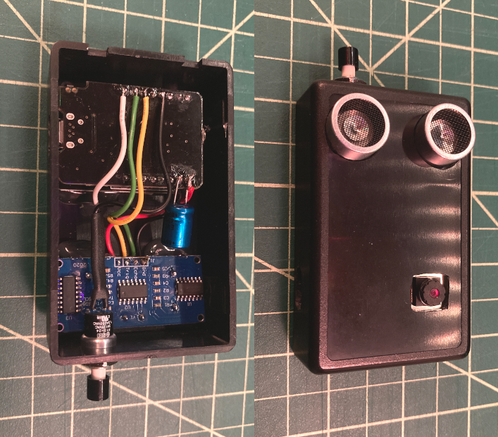
The completed project box was installed in its location, along with an external LED light source and a wireless 433Mhz temperature and humidity sensor. The light source would be reflected off any water accumulating and be visible with camera.
Originally the design was going to use moisture sensors at set levels to determine flood levels. However this design was flawed because the moisture sensors have a short service life and require frequent replacement. The ultrasonic sensor reduces servicing and offers reliability and higher accuracy.
Next is the MQTT broker and Node-Red. There isn’t much other than installing a MQTT broker service for that portion. I won’t get into security or access controls here. Suffice it to say, once a broker is up and running, not much else needs to be done.
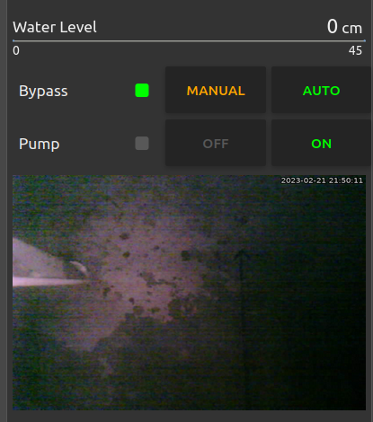
In contrast, Node-Red is the heavy lifter for this project. It presents the video feed from the ESP32-Cam on the Node-Red web interface using FFMpeg. It subscribes to the ESP32-Cam modules published feeds and displays that on the web UI. The HC-SR04 readings are published and Node-Red processes those values to display water depth. Those readings are also evaluated by Node-Red and it then publishes actions based on user input and defined thresholds. Besides external monitors to verify all is online and working, Node-Red also monitors the online status of the ESP32-Cam module. Here is a closer look at each flow in Node-Red.

Lets start with the video feed flow. The first node is an inject node that triggers at an interval every 10 seconds. The flow then goes to a change node that changes the msg.payload to a string that contains the path and name of an image file “/usr/share/node-red-static/ESP32-Cam_WaterMonitor.jpg”. This then feeds into an exec node that contains the following command.
ffmpeg -y -i http://<IP_Address_of_ESP32-Cam_WaterMonitor> -vf "pp=al, drawtext=fontfile=/usr/share/fonts/dejavu/DejaVuSans-Bold.ttf: text='%{localtime\}': fontcolor=white@0.8: fontsize=18: bordercolor=black@0.8: borderw=2: x=608: y=7" -vframes 1 -f image2pipe -vcodec png -
That command runs FFMpeg and uses the ESP32-Cam as the source. The command also applies a video filter to draw text using a defined font, size, and weight at a designated position of the image. The text contains a timestamp that is overlayed on the image. The exec node then branches to 2 other nodes. Both of these are function nodes, one checks that the msg.payload.buffer is not empty, not in a fault, the other checks if the msg.payload.code value equals “1”, in a fault. If the flow payload is in a fault, then a read file node references a file and its path “/usr/share/node-red-static/ColorBars.jpg”. It’s output is set as “a single utf8 string” with encoding set as base64. If the flow payload is not in a fault, then a base64 node is used with an action of Encode as Base64 for the msg.payload. Both of theses nodes feed into a function template node where the msg.payload is fed into the following template.
<img width="360px" height="240px" src="data:image/jpg;base64,{{{payload}}}">
The final node in the flow is a dashboard template node. This places the msg.payload inside the template for displaying on the WebUI with this template code.
<div ng-bind-html="msg.payload"></div>
As you can see, providing video feeds in the Node-Red WebUI is rather involving. Fortunately, processing the MQTT feed from the ESP32-Cam isn’t as much trouble. The Arduino code above had these lines that directs the ESP32-Cam to publish its uptime, wifi signal strength, firmware version, and wifi network mac address.
client.publish("ESP32-Cam_WaterMonitor/Firmware", "ESP32-Cam_WaterMonitor_Ver_1");
String StringUptime = String(millis());
client.publish("ESP32-Cam_WaterMonitor/Uptime", StringUptime.c_str());
String StringHWAddress = String(WiFi.macAddress());
client.publish("ESP32-Cam_WaterMonitor/HWAddress", StringHWAddress.c_str());
String StringWifiSignal = String(WiFi.RSSI());
client.publish("ESP32-Cam_WaterMonitor/WifiSignal",StringWifiSignal.c_str());
The firmware topic is statically set text, whereas the other values are read during run time and published. Node red uses a mqtt in node to subscribe to the specific topic of each. Here is a list of them.
- ESP32-Cam_WaterMonitor/Firmware
- ESP32-Cam_WaterMonitor/HWAddress
- ESP32-Cam_WaterMonitor/WifiSignal
- ESP32-Cam_WaterMonitor/Uptime
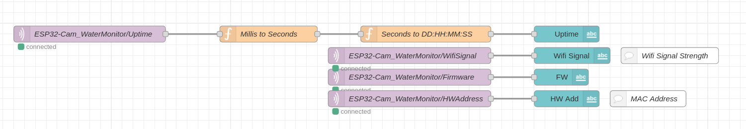
The top 3 flow directly into individual dashboard text nodes containing the label and value format {{msg.payload}}. The bottom uptime node flows into a function node to convert millis into seconds. Here is the code for that function.
var millis = msg.payload;
var S = millis / 1000;
var seconds = Math.floor(S);
msg.payload = seconds;
return msg;
The payload then flows to another function node that converts the seconds tally into a DD:HH:MM:SS readable format. Here is the code for that function.
var totalNumberOfSeconds =  msg.payload;
var days = parseInt( totalNumberOfSeconds / 86400 );
var hours = parseInt (( totalNumberOfSeconds - ( days * 86400 )) / 3600  );
var minutes = parseInt ((totalNumberOfSeconds - ((hours * 3600)+( days * 86400 ))) / 60 );
var seconds = parseInt(totalNumberOfSeconds - ((hours * 3600) + (minutes * 60)+( days * 86400 )));
var result = (days < 10 ? "0" + days : days) + " Days " + (hours < 10 ? "0" + hours : hours) + ":" + (minutes < 10 ? "0" + minutes : minutes) + ":" + (seconds  < 10 ? "0" + seconds : seconds);
msg.payload=result;
return msg;
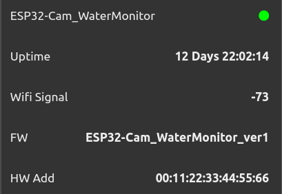
This then flows into its dashboard text node in similar fashion as the above 3 mentioned earlier. The use of MQTT feeds on the ESP32-Cam module and in Node-Red is powerful and it has great potential beyond the scope of this project.
The next flow is a system status monitor of the ESP32-Cam module network connection. This flow starts with a ping node that has an interval of every 15 seconds. It then flows into a change node that replaces the msg.payload false or true values to string values of On or Off respectively. The flow then branches out in 2 directions with the first flow feeding a function node with the following code.
msg.color = (msg.payload === "On")?"red":"lime";
return msg;

This then flows into a dashboard text node with the value format set with these parameters.
<font color={{msg.color}} ><i class="fa fa-circle" style="font-size:24px;"></i></font>
The label in this node is also defined. The final results are a LED like indicator on the WebUI next to the label. The other branch from the change node mentioned earlier is sent to a separate flow that sends alerts to staff.
The Arduino code above also had a line that defined the mqtt published reading from the HC-SR04 ultrasonic ranging module.
client.publish("ESP32-Cam_WaterMonitor/Level", MeasureLevelCM.c_str());
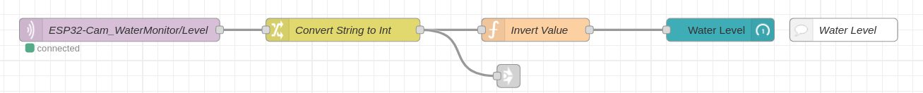
The Node-Red flow here start with a mqtt in node and it subscribes to the topic “ESP32-Cam_WaterMonitor/Level”. This then flows into a change node converting the msg.payload into an expression $number(payload), thus converting the string into an integer. The flow branches in 2 directions. The second branch will be covered later in the action flow. The first continues to a function node where a formula is applied to convert distance to a baseline of zero, here is the code in that function.
msg.payload = (msg.payload*(-1))+41;
return msg;
The next node is a dashboard artless-guage node that displays the reading as a linear bar. The minimum and maximum range values are set here.
The last flow used in Node-Red will make use of context based variables. This will be the most complex flow thus far. Context based variables are an extremely powerful tool that can leverage the potential of Node-Red. Earlier on the HC-SR04 ultrasonic ranging module reading was converted to an integer. Here that value flows into a function node that processes the value with a formula and stores the reading as a variable. Here is the instruction in the node.
msg.payload = (msg.payload*(-1))+41;

var reading=context.get("reading");

reading=msg.payload;
context.set("reading",reading);

global.set("globalreading",reading);
return msg;
As the readings are updated on the ESP32-Cam module and published to the MQTT broker, Node-Red will receive those updated readings and store the new values into the variable defined. This will be useful because a separate flow will reference that variable.
That separate flow will start with an inject node that is set to repeat at an interval every 3 seconds. It will then flow into a function node that gathers a host of variables and sets the msg.payload based on the variable values. Here is the function code.
var bypass=global.get("globalbypass");
var action=global.get("globalaction");
var reading=global.get("globalreading");
// var pump=0;

if (bypass=="Auto" && reading<=0)
    pump=0;
if (bypass=="Auto" && reading>=2)
    pump=1;

if (bypass=="Manual" && action=="Off")
    pump=0;
if (bypass=="Manual" && action=="On")
    pump=1;

msg.payload=pump;
return msg;
This then flows into 2 separate function nodes that have the following code.
// Pump On Operator
var pump=msg.payload;

if (pump==1)
    msg.payload=pump;
else { return }

return msg;

// Pump Off Operator
var pump=msg.payload;

if (pump==0)
    msg.payload=pump;
else { return }

return msg;
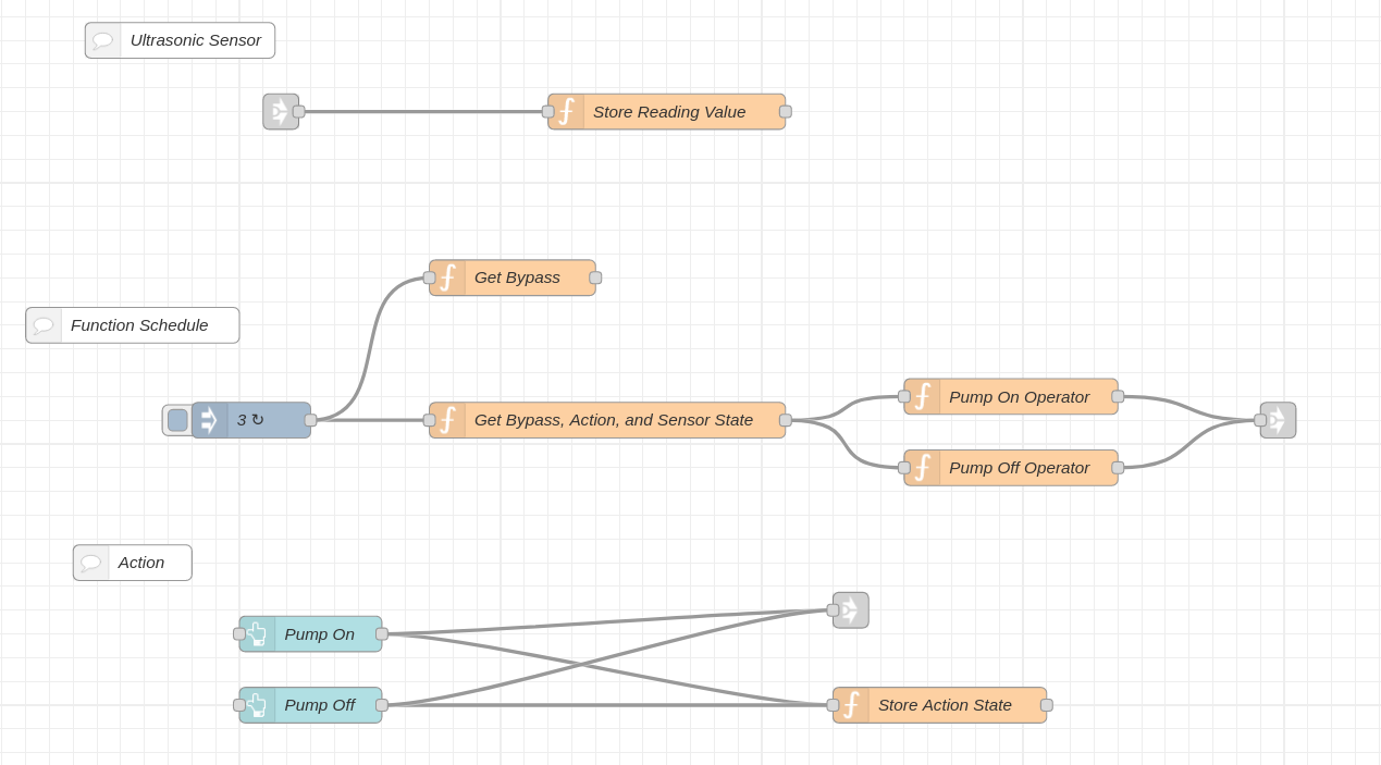
The results of these nodes are passed to the mqtt broker. Parallel to this there are 2 dashboard button nodes, each of which publish a topic value to the mqtt broker. The end result is turn the water pump on or off.
It was mentioned earlier that Node-Red was the heavy lifter and that was no exaggeration. The key takeaway is how context variables can be dynamically changed and referenced at any point in flows. Having that available is what makes controlling a water pump under any number of circumstances possible. Although it can be a difficult topic for some to grasp initially, it takes the burden off of the ESP32-Cam module and for that it’s invaluable. For more details, reference these links.
https://techexplorations.com/guides/esp32/node-red-esp32-project/node-red-messages-variables/
https://nodered.org/docs/user-guide/environment-variables
https://youtu.be/h6321UBATps