CO Detector Hack – Part 3
In this post I’ll cover how to interface with the CO Detector I covered in earlier posts. Based on the measurements I did, the CO Detector has 4 outputs and 1 input the we can interface with. Here is a list of these interfaces along with a brief description.
SW1 – Test Button
VDD1 – Power On
ICSPDAT/RS232 – Data
LED1-A – Status LED
H1-A – Alert Buzzer
One thing that I like to do before building a bread board circuit is to draw out a schematic. It provides a reference should I need to rebuild it at a later time.
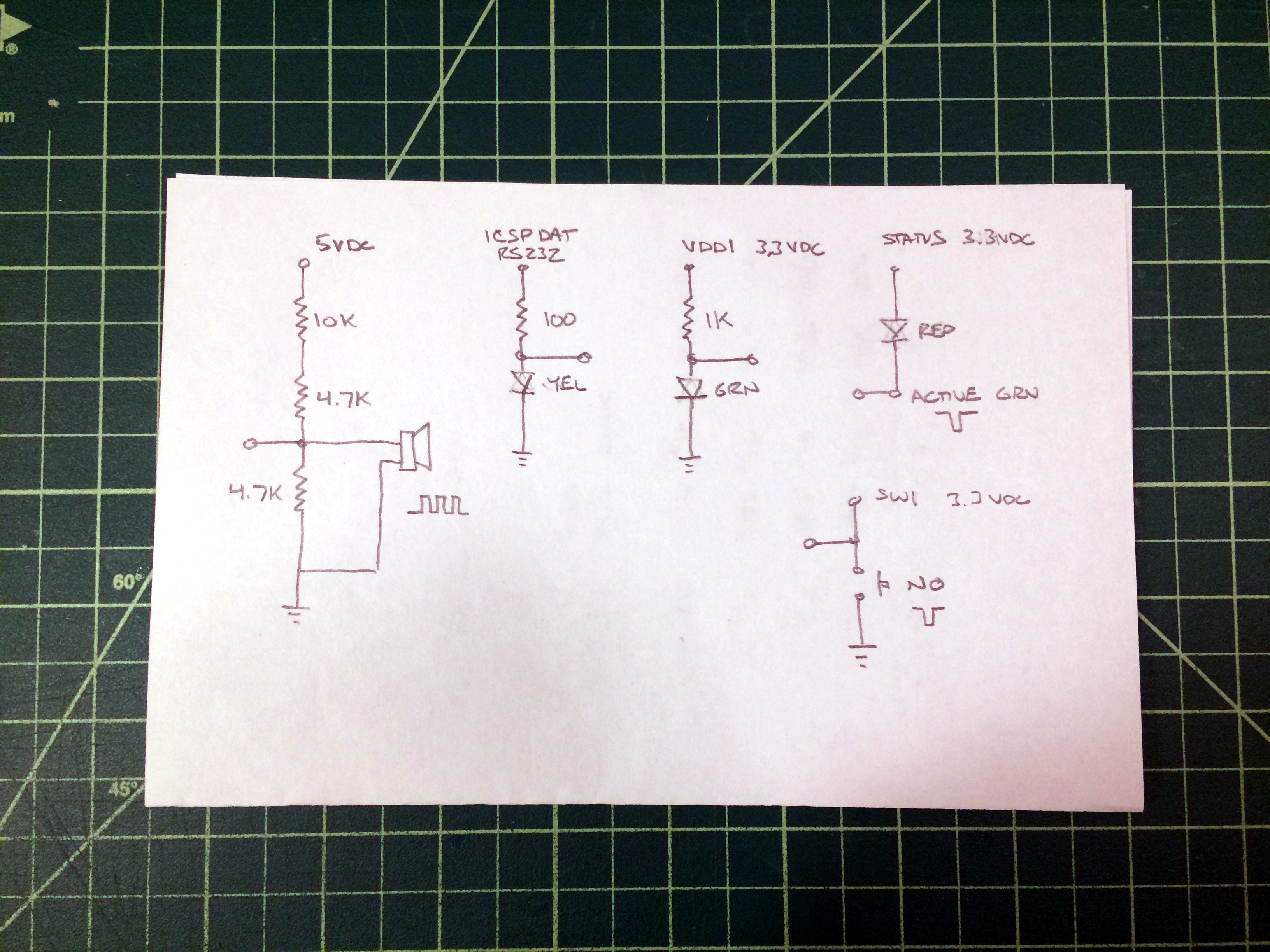
First I’ll start with the single input interface. The test button on the CO Detector is used to verify that the alarm will sound. It should be noted that this test does not verify that the unit is working. That might seem odd but this is the case with most CO detectors. The push button triggers the logic circuit which then in turn sends pulses to the alarm buzzer and status LED. It verifies that the battery has enough power to operate the device and that the alarm makes a sound, that is it.
The SW1 button completes a circuit to ground that has a normally high state. This means that we can attach any type of micro controller or similar device to perform the same function of the switch. In my example, I have another external push button switch on a bread board. It operates the same way that the on board switch does.
When I press and hold the switch, the status led and alert buzzer activate and dmake a single short pulse. I can then release the switch and the unit logic then continues to send 4 test pulses two times to both the status led and alert buzzer.
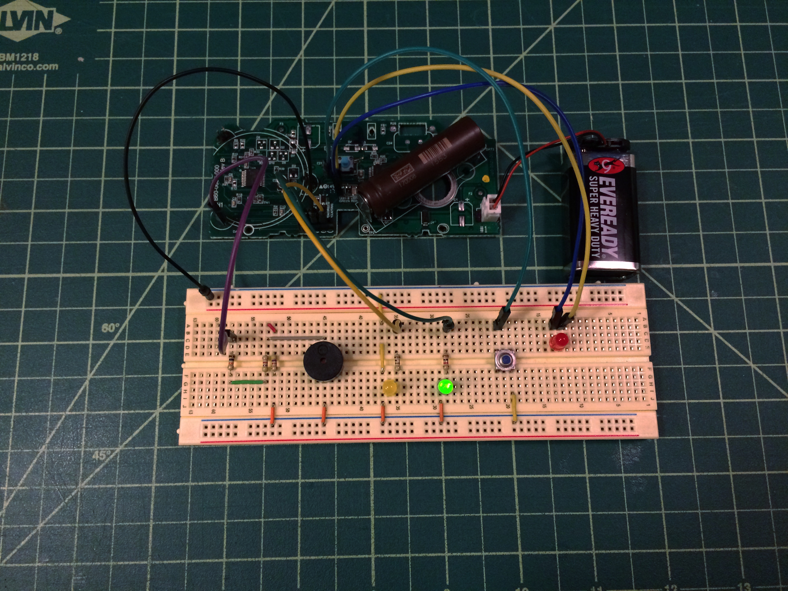
The first output interface that I’ll cover is VDD1. This is the logic high level and is useful to tell if the device has power or not. I have connected that pin through a 1k ohm resistor then through a green led on my bread board. Again, this pin can be sent to an input pin on a micro controller to monitor the status of the pin.
When power is applied to the board, the green led on my breadboard is lit. It remains lit throughout the operation of the board.
The second output interface is a yellow led to indicate the presence of a data transmission on the ICSPDAT/RS232 pin. It normally has a low state when no data is transmitted. The data transmissions bring the voltage up to 3.3 vdc for brief periods of time. I’m using a 100 ohm resistor so the led is brighter, otherwise it would be difficult to spot activity.
The next output interface is LED1-A. This interface has 2 connections with each side connected to either side of a surface mounted red led on the board. I soldered terminal pins to these pads as a way to jumper off it. Both of the pins are normally high at a logic 3.3 vdc level when the led is off. When the led is lit, the level on both pins drops to low.
I’ve taken both pins and connected another red led in parallel on my bread board. It turns on and off exactly when the on board led does. The change in state on this pin can be monitored to indicate a status change. It should be noted that the status led pulses are defined to indicate certain conditions. These conditions can be monitored by a micro controller to take further action. Here is a list of the conditions and types of led pulses that can occur.
1 pulse every 15 seconds – normal operation
4 pulses, pause, 4 pulses, stop – alarm test
constant pulses – alarm active
So far all of out interfaces have operated in the 3.3 vdc logic range. The last output interface does not follow this same scheme. The alert buzzer lead H1-A has a higher 5.09 vdc range. This higher voltage doesn’t appear to be regulated, so it will vary based on levels supplied by the battery.
The alarm buzzer, like the status led, operates under certain conditions. At rest the pin H1-A is normally low. When active, it goes high at a frequency around 400 hz for a period of time, these are called chirps for short bursts and beeps for longer ones. These chirp and beep conditions are the indication of how the CO Detector is operating.
1 chirp per minute – replace battery
3 chirps per minute – malfunction, replace alarm
5 chirps per minute – end of life, replace alarm
4 beeps at a constant rate – CO is in alarm
Monitoring the interface with a micro controller or other device will require some special considerations. The voltage levels will need to be adjusted so the monitoring device can handle it. Using some type of isolation circuit would be best, such as a photo diode. The voltage from the alarm buzzer would drive a led that is detected by a photo diode. The photo diode would use safer logic levels to indicate state change on this output. For my example, I used a voltage divider and connected a speaker to a branch from the voltage divider. It produces lower sound levels for testing purposes.
Although much of the detail in this post, as well as the previous two were specific to this particular CO Detector, the method to identify interfaces is universal for most electronic devices. It should be noted that tampering with any electronic device requires attention to safety. You should not make any attempts to open electronic equipment unless you understand the risks to people or equipment as well as the risk of fire. Even with all of these precautions taken, once you open a device the manufacturer may void all guarantee that the device will operate as expected. This is especially important to understand for devices that provide a critical function, such as CO detection, where failure could result in injury or death. The purpose of this post is merely to demonstrate how identify and interface with CO detector with the intent to understand its underlaying operation.