ESP-32 Flight Datalogger – Hardware Build
Since the ESP32-Cam project was going to be installed on a remote controlled plane, keeping things as light as possible was the primary concern. This required a tally of what each item weighed and how best to build around that.
All aircraft have a center of gravity that is used as a reference point. That point is where the aircraft balances front to back or side to side. Any change in that point can influence how the aircraft will fly. A good saying that describes this is that a nose heavy plane doesn’t fly well, a tail heavy plane doesn’t fly long. The build had to take this into account and be done as to maintain the original center of gravity.
Each item that made up the project was weighed. The electronics, battery, power supply, wiring, and control switches were all weighed. The GPS module and battery accounted for most of the weight. The GPS module was small enough to be fitted under the canopy. This left the battery and remaining items. They had similar weight so placing them in separate pylons seemed to make the most sense in regard to maintaining center of gravity.
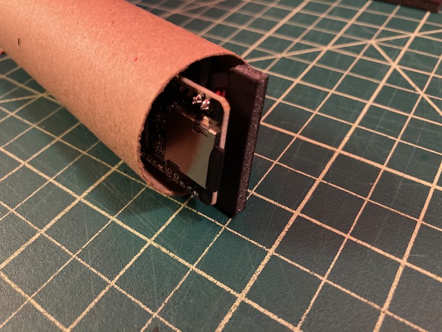
The battery would be housed in one pylon, while the remaining electronic items would be in the other. Each pylon would be mounted under each side of the wing, next to the fuselage. The space taken up by the ESP32-Cam module when mounted on backing required a tube that was 38mm in diameter. The same diameter tube would be used for the battery. Attaching both pylons involved wrapping a long rubber band around the fuselage forward and aft of the wings. This principle was tested with a similarly sized glider, which worked well.
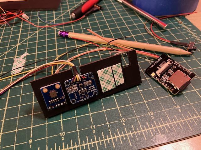
The electronics pylon contained a 3mm foam core backing that had each of the electronic components attached with double sided 1mm adhesive. Before attaching the components, wiring was soldered and shrink tubing was used to strengthen and protect the wiring leads. The function of the wiring was matched with its color so it could later be joined and capped once all the components were installed. Continuity and voltage testing was done with regularity throughout the build. The GPS module and battery had a connector which was matched on the electronics for connecting when ready for flight.
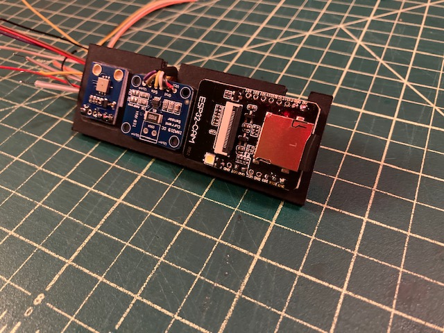
With all of the electronics built and mounted on the backing, a test of the system was run without any issues. It was ready for flight.
The deadline was days away and the bulk of the build was done. However, the pylons still needed end caps, preferably ones that were aerodynamic. The problem with this was the amount of time left before the deadline and the unique nature of the hardware. The next section will cover how this problem was addressed with a 3D printer and community sourced parts.