GPS Mapping with Viking using ESP-Now and GPSd
The last post (https://www.cloudacm.com/?p=4185) ended with a video titled “Decoding GPS using an RTL SDR Receiver” that was posted August of 2020. The 2 software requirements for this method are RTKLIB (https://www.rtklib.com/rtklib_tutorial.htm) and GNSS-SDRLIB (https://github.com/taroz/GNSS-SDRLIB). The video mentioned that Google Maps didn’t display, however there was mention in comments about an API requirement. The video did introduce the option to port the output to another mapping program, one of which is Viking.
On a side note, I found this video about Viking navigation to be both fascinating and enlightening. It stands to reason the heritage of the Viking explorers inspired the name of the mapping software covered in this post.
The mapping software mentioned earlier called Viking can be ran on Linux or Windows. However, real-time GPS positioning is only available in Linux at the time of this writing. More details can be found here, https://sourceforge.net/projects/viking/ as well as here, https://wiki.openstreetmap.org/wiki/Viking. The manual can be downloaded here, https://sourceforge.net/projects/viking/files/viking.pdf
Viking uses layers, similar to GIMP or Photoshop. Each layer contains a specific type of information. The fundamental layer to
introduce here is the map layer. Viking has several map types to choose from, I have found OpenStreetMap Mapnik the most
suitable for my needs, see https://mapnik.org/ for more details. Open Viking then Add new layer, Map > Map Type OpenStreetMap (Mapnik) at 129 alpha. I like to have the layer semitransparent before I finalize the display. Viking can display GPS data in its raw NMEA format, either from file or real-time. This is extremely useful when gathering GPS data from simple devices, such as the Goouuu Tech GT-U7 ublox GPS module. Here is a video demonstration of the Viking interface.
The Goouuu Tech GT-U7 ublox GPS module can be purchased for less than $15. The datasheet can be found here, https://manuals.plus/goouuu/goouuu-tech-gt-u7-gps-modules.pdf. Here is a video demonstrating its use with an Arduino.
The video above demonstrates the processed results from the GT-U7 using the TinyGPS++ library. Natively, the module outputs NMEA sentences, a sanitized example is below. Information about NMEA sentences can be found here, https://gpsd.gitlab.io/gpsd/NMEA.html
$GPRMC,......00,A,.....,1.313,,.....,,,A*67
$GPVTG,,T,,M,1.313,N,2.433,K,A*25
$GPGGA,.......00,......,1,03,4.00,58.0,M,-18.8,M,,*5D
$GPGSA,A,2,14,30,17,,,,,,,,,,4.12,4.00,1.00*01
$GPGSV,3,1,09,05,03,258,,08,,,23,13,53,285,,14,84,294,25*48
$GPGSV,3,2,09,15,27,307,22,17,39,173,20,19,,,14,21,18,072,25*4A
$GPGSV,3,3,09,30,71,113,27*43
$GPGLL,......,.......00,A,A*7E
Viewing real-time NMEA source data in Viking will require GPSd. This is because Viking does not support native NMEA sources through a serial connection. The NMEA sources are only supported through a network pipe, which GPSd provides. Details about GPSd can be found here, https://gpsd.io/
This video provides install and config steps to get GPSd running.
It may not be suitable to have the GT-U7 module directly attached to a Linux host due to environmental limits. Capturing GPS data can be done with a ESP32-Cam module. The serial stream is monitored by the ESP32-Cam module and any inbound serial data is then written to the microSD media. This code can be used to do just that.
/**

SerialStreamToMicroSD_Ver1.ino
Captures serial stream on inbound serial pin and stores on micro-SD
July 24th, 2022 - 18:00

Thanks
https://stackoverflow.com/questions/38278755/write-from-serial-port-to-sd-card
https://stackoverflow.com/questions/5697047/convert-serial-read-into-a-useable-string-using-arduino

ESP32-CAM connections required for standalone mode
VCC = 5V DC
GND = Ground
RXD = TXD of GPS module

Optional connection when using serial output
TXD = RXD of FTDI USB module

**/


// Libraries
#include "Arduino.h"
#include "FS.h"     // SD Card ESP32
#include "SD_MMC.h"     // SD Card ESP32

// ESP32-CAM GPIOs
#define RXD 3
#define TXD 0     // Not used when not connected to serial output


// Variables and Constants

String inData;
const char* GPSReadings = "/GPS_NMEA_Data.txt";

// Routines and Subroutines


// Hardware Initialization Routine
void HardwareInit()
{
  // Note the format for setting a serial port is as follows:
  // Serial.begin(baud-rate, protocol, RX pin, TX pin);
  // initialize serial:
  Serial.begin(9600, SERIAL_8N1, RXD, TXD);
  delay(250);  // Just a little delay
}


void StartupMicrSD()
{
   if(!SD_MMC.begin()){
        return;
    }
    uint8_t cardType = SD_MMC.cardType();

    if(cardType == CARD_NONE){
        return;
    }

}

//Append to the end of file in SD card
void appendFile(fs::FS &fs, const char * path, const char * message){

    File = fs.open(path, FILE_APPEND);
    if(!file){
        return;
    }
    if(file.print(message)){
    } else {
    }
}


// Inbound Serial Data Processing
void InboundSerialData()
{
    if(Serial.available())                                   // if there is data coming
  {
    String inputString = Serial.readStringUntil('\n');         // read string until meet newline character
    Serial.println(inputString);                  // send action to Serial Monitor
    appendFile(SD_MMC, GPSReadings, inputString.c_str());
    appendFile(SD_MMC, GPSReadings, "\n");
  }
}


void setup()
{
  HardwareInit();
  StartupMicrSD();
}


void loop()
{
  InboundSerialData();
}
Although this method will capture the GPS stream, real-time processing is not available. One solution to this is to link two ESP32-CAM modules together using a proprietary protocol that is native to Espressif ESP modules. This protocol is called ESP-Now. Essentially, ESP-Now will provide a tethered connection from the GT-U7 module to the Linux computer running GPSd and Viking using the 2 ESP32-CAM modules. The ESP32-Cam module that has the GT-U7 module will be called the Sender. The ESP32-Cam module that is attached to the Linux host will be called the Receiver. The Linux computer will for all intents and purposes appear to have the GT-U7 directly attached. The manual for ESP-Now can be found here, https://www.espressif.com/sites/default/files/documentation/esp-now_user_guide_en.pdf. This video provides an intro and use case for ESP-Now.
Here is the code base used for the Sender.
/*
  Rui Santos
  Complete project details at https://RandomNerdTutorials.com/esp-now-esp32-arduino-ide/

  Permission is hereby granted, free of charge, to any person obtaining a copy
  of this software and associated documentation files.

  The above copyright notice and this permission notice shall be included in all
  copies or substantial portions of the Software.

  Info on encryption
  https://www.electrosoftcloud.com/en/security-on-your-esp32-with-esp-now/

  This might be a better approach.
  https://www.survivingwithandroid.com/esp-now-esp32-esp8266/
  Reason - this code base uses the library extensively and much of the inner workings
  are hidden
*/

// Declarations and Variables

#include "Arduino.h"
#include "FS.h"                // SD Card ESP32
#include "SD_MMC.h"            // SD Card ESP32
const char* GPSReadings = "/GPS_Sender.txt";

#include <esp_now.h>
#include <WiFi.h>
// ESP32-CAM GPIOs
#define RXD 3
#define TXD 0

// REPLACE WITH YOUR RECEIVER MAC Address
// Receiver
// BOARD1
// R labelled Board - Connected to Laptop for Receiving GPS ESP-Now Messages
// ESP Board MAC Address:  FF:FF:FF:FF:FF:FF
// {0xFF, 0xFF, 0xFF, 0xFF, 0xFF, 0xFF}
uint8_t broadcastAddress[] = {0xFF, 0xFF, 0xFF, 0xFF, 0xFF, 0xFF};

// Structure example to send data
// Must match the receiver structure
typedef struct struct_message {
  char GpsData[128];
} struct_message;

// Create a struct_message called myData
struct_message myData;

esp_now_peer_info_t peerInfo;

// callback when data is sent
void OnDataSent(const uint8_t *mac_addr, esp_now_send_status_t status) {
}


void HardwareSetup()
{
  // Note the format for setting a serial port is as follows:
  // Serial.begin(baud-rate, protocol, RX pin, TX pin);
  // initialize serial:
  Serial.begin(9600, SERIAL_8N1, RXD, TXD);

  // Set device as a Wi-Fi Station
  WiFi.mode(WIFI_STA);

  // Init ESP-NOW
  if (esp_now_init() != ESP_OK) {
    Serial.println("Falied initializing ESP-NOW");
    return;
  }

  // Once ESPNow is successfully Init, we will register for Send CB to
  // get the status of Transmitted packet
  esp_now_register_send_cb(OnDataSent);

  // Register peer
  memcpy(peerInfo.peer_addr, broadcastAddress, 6);
  peerInfo.channel = 0;
  peerInfo.encrypt = false;

  // Add peer
  if (esp_now_add_peer(&peerInfo) != ESP_OK){
    Serial.println("Falied to add peer");
    return;
  }
}

void StartupMicrSD()
{
   if(!SD_MMC.begin()){
        return;
    }
    uint8_t cardType = SD_MMC.cardType();

    if(cardType == CARD_NONE){
        return;
    }

}


//Append to the end of file in SD card
void appendFile(fs::FS &fs, const char * path, const char * message){

    File = fs.open(path, FILE_APPEND);
    if(!file){
        return;
    }
    if(file.print(message)){
    } else {
    }
}


void setup() {
StartupMicrSD();
HardwareSetup();
}

void loop() {

    if(Serial.available())                                   // if there is data coming
  {
    String inputString = Serial.readStringUntil('\n');         // read string until meet newline character
    Serial.println(inputString);                  // send action to Serial Monitor
    appendFile(SD_MMC, GPSReadings, inputString.c_str());
    appendFile(SD_MMC, GPSReadings, "\n");
    inputString.toCharArray(myData.GpsData, 128);
    esp_err_t result = esp_now_send(broadcastAddress, (uint8_t *) &myData, sizeof(myData));

  }
}

/*
  Some Note
*/
Here is the code base used for the Receiver.
/*
  Rui Santos
  Complete project details at https://RandomNerdTutorials.com/esp-now-esp32-arduino-ide/

  Permission is hereby granted, free of charge, to any person obtaining a copy
  of this software and associated documentation files.

  The above copyright notice and this permission notice shall be included in all
  copies or substantial portions of the Software.
*/

// Declarations and Variables

#include "Arduino.h"
#include "FS.h"                // SD Card ESP32
#include "SD_MMC.h"            // SD Card ESP32
const char* GPSReadings = "/GPS_Receiver.txt";

#include <esp_now.h>
#include <WiFi.h>
// ESP32-CAM GPIOs
#define RXD 3
#define TXD 0
String inputString = "";

// Structure example to receive data
// Must match the sender structure
typedef struct struct_message {
    char GpsData[128];
} struct_message;

// Create a struct_message called myData
struct_message myData;

// callback function that will be executed when data is received
void OnDataRecv(const uint8_t * mac, const uint8_t *incomingData, int len) {
  memcpy(&myData, incomingData, sizeof(myData));
  String inputString = String(myData.GpsData);
  Serial.println(inputString);
  appendFile(SD_MMC, GPSReadings, inputString.c_str());
  appendFile(SD_MMC, GPSReadings, "\n");
}

void HardwareSetup()
{
  // Note the format for setting a serial port is as follows:
  // Serial.begin(baud-rate, protocol, RX pin, TX pin);
  // initialize serial:
  Serial.begin(9600, SERIAL_8N1, RXD, TXD);

  // Set device as a Wi-Fi Station
  WiFi.mode(WIFI_STA);

  // Init ESP-NOW
  if (esp_now_init() != ESP_OK) {
    Serial.println("Falied initializing ESP-NOW");
    return;
  }

  // Once ESPNow is successfully Init, we will register for recv CB to
  // get recv packer info
  esp_now_register_recv_cb(OnDataRecv);
}


void StartupMicrSD()
{
   if(!SD_MMC.begin()){
        return;
    }
    uint8_t cardType = SD_MMC.cardType();

    if(cardType == CARD_NONE){
        return;
    }

}


//Append to the end of file in SD card
void appendFile(fs::FS &fs, const char * path, const char * message){

    File = fs.open(path, FILE_APPEND);
    if(!file){
        return;
    }
    if(file.print(message)){
    } else {
    }
}


void setup() {
StartupMicrSD();
HardwareSetup();
}

void loop() {

}
Initially there were some issues when using the ESP32-Cam USB programing board. The correct wiring should be limited to Ground, 5V, RXD, and TXD between the ESP32-Cam module and the USB programing board. Under normal operation, when both the Sender and Receiver are powered on and in range of each other, the GPS stream should be captured on both module’s microSD cards. With the Receiver attached to the Linux host, GPSd can be configured to use the Receiver as its GPS NMEA source. Viking can now be configured to connect to GPSd for live plotting. To do so, following these steps.
Open Viking
Add all new layers to Top Layer
Add new layer, GPS > Realtime Tracking Mode tab
Check the following items:
Recording tracks
Jump to current position on start
Moving Map Method – Keep vehicle on screen
Update Statusbar
Auto Connect
Gpsd Host: localhost
Gpsd Port: 2947
Gpsd Retry Interval (seconds) 10
Add new layer, Map > Map Type OpenStreetMap (Mapnik) at 128 alpha
The GPS stream can also be validated with GPSMon. GPSMon is part of GPSd and can be ran from the command line on the Linux host. Here is a video of the GPSd config and GPSMon interface.
The GSV section is interesting because it contains $GPGSV sentences which are GPS satellite data location and SN ratio levels. Here is an example of that window.
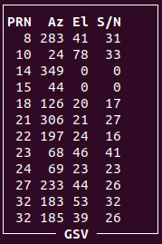
These values can be plotted with Python using MatPlot and NumPy to create a polar projection of the satellite location and signal strength. Here is an example.
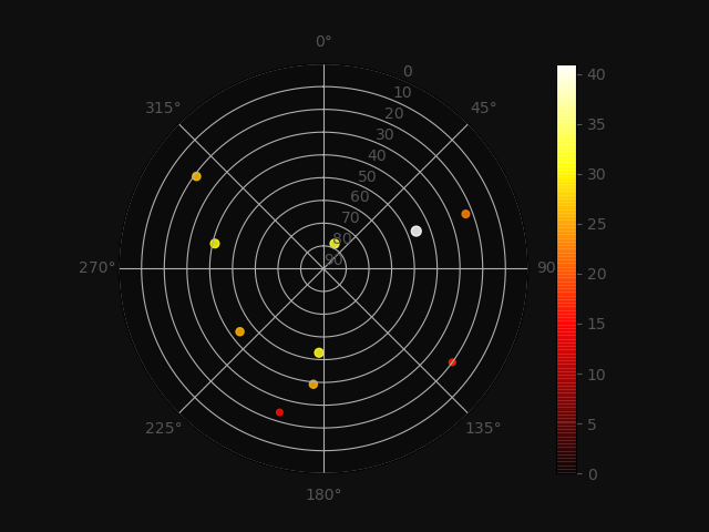
Here is the python code used to create the plot above.
"""
Demo of scatter plot on a polar axis.

Size increases radially in this example and color increases with angle (just to
verify the symbols are being scattered correctly).
"""
import numpy as np
import matplotlib.pyplot as plt

Azimuth = [0, 283, 24, 349, 44, 126, 306, 197, 68, 69, 233, 183, 185]
Elevation = [0, 41, 78, 0, 0, 20, 21, 24, 46, 23, 44, 53, 39]
SignalNoise = [0, 31, 33, 0, 0, 17, 27, 16, 41, 23, 26, 32, 26]

Elevation = (np.array(Elevation))
Azimuth = np.radians(np.array(Azimuth))
SignalNoise = np.array(SignalNoise)
colors = SignalNoise

plt.figure(facecolor='#0f0f0f') # Set background color of the outer
color = '#555555'
plt.rcParams['text.color'] = color
plt.rcParams['axes.labelcolor'] = color
plt.rcParams['xtick.color'] = color
plt.rcParams['ytick.color'] = color

ax = plt.subplot(111, polar=True) # Set as polar plot
ax.set_ylim(90,0) # Set range of Elevation and direction of scale
ax.set_theta_zero_location('N') # Set Azimuth 0 to top of plot
ax.set_theta_direction(-1) # Set Azimuth direction of N, E, S, W in clockwise direction
c = plt.scatter(Azimuth, Elevation, c=colors, s=SignalNoise, cmap=plt.cm.hot) # Set polar plot type to scatter and set color
c.set_alpha(0.85)
ax.set_facecolor('#0b0b0b')
cbar = plt.colorbar()

# plt.show()
plt.savefig("GPS_SatPlot_Demo_Scatter_Test1b.png", facecolor='#0f0f0f')
The plots can be combined with FFMpeg to create a video that reveals the motion of the satellites over time, along changes in signal strength. Another python tool available is gpsclient, available here https://pypi.org/project/gpsdclient/. I won’t cover this here since it is more a side note.
Another program that runs on Linux that has been discussed in earlier posts is GPredict. This program provides an approximate view of where satellites are located. More details about the program can be found here, https://sourceforge.net/projects/gpredict/files/Gpredict/1.3/gpredict-user-manual-1.3.pdf. The following video was created to demonstrate how GPredict plots satellite motion over time. These are the FFMpeg screen capture commands used for the video below.
ffmpeg -video_size 1920x1080 -framerate .033 -f x11grab -i :0.0+1920,0 GPredict_1.mp4
ffmpeg -i GPredict_1.mp4 -r 15 -filter:v "setpts=0.03*PTS" GPredict_2.mp4
ffmpeg -i GPredict_2.mp4 -r 15 -filter:v "setpts=0.03*PTS" GPredict_3.mp4
Here is a video demonstrating some basic configurations of GPredict and viewing options. I used FFMpeg to trim the length and size from an original desktop capture with these commands.
ffmpeg -video_size 1920x1080 -framerate 15 -f x11grab -i :0.0+1920,0 GPredict_Demo_15FPS.mp4
ffmpeg -ss 00:00:13 -to 00:05:22 -i GPredict_Demo_15FPS.mp4 -filter:v "crop=1391:893:140:123" GPredict_Demo1_15FPS.mp4
This video demonstrates using SDR and Viking to capture and plot Weather balloon Radiosonde GPS data.
The demonstration above used these process commands below, with some description of each. However, I wasn’t able to source all of them, so those details are lacking. It would take more research to replicate, which is outside the scope of this post.
socat -d -d pty,raw,echo=0 pty,raw,b4800,echo=0
//    Socat is a flexible, multi-purpose relay tool. Its purpose is to establish a relationship between two data sources, where each data source can be a file, a Unix socket, UDP, TCP, or standard input.

gpsd -D2 -b -n -N /dev/pts/19
gpspipe -r localhost:2947
sox -t oss /dev/dsp -t wav - lowpass 2400 highpass 20 2>/dev/null | ./dfm06 -i --ecc -vv | ./pos2nmea.pl > /dev/pts/11
pos2nmea.pl – https://github.com/happysat/RS-Decoder-for-Radiosondes-in-Ubuntu-Linux (the dreaded 404 not found message)
dfm06 – No github page
gpspipe – https://gpsd.io/gpspipe.html, part of GPSd
sox – https://sox.sourceforge.net/soxformat.html
Here is yet another example of inexpensive hardware leveraging open-source software and public standards to give the learned a richer view of the world. We all have a nonprofit association composed of manufacturers, distributors, dealers, educational institutions, and others interested in peripheral marine electronics occupations to thank for the basis of commercial GPS, which is NMEA (The National Marine and Electronics Association). Here is a link to that organization’s website, https://www.nmea.org/
Another public standard worth mentioning is ADS-B (Automatic Dependent Surveillance–Broadcast). Here is a video that introduces the basics of its use.