Signals – Digital, Analog, and PWM
In this post I’ll be covering fundamental electronic signals. These will establish a foundation for us to work from as I begin to cover more advanced signaling technology. First, we will cover digital signals. These are the most basic since they are either on or off. Next, we cover RC Time circuits which allow us to use a digital port to read an analog condition. We’ll follow that up with analog signals and how we read them electronically. Next, I’ll cover pulse width modulation (PWM) as a way for us to create analog signals from a digital source. Lastly, we’ll explore conditioning circuits that work with analog signals to bring them into a working headroom for our devices.
What are signals and what purpose do they serve? Signals are essentially voltage levels and we use them to do a whole host of things like, turn on a light, listen to music, adjust the temperature of a room, and much more. I won’t be going into specifics, but I will be focusing our attention of signals towards those used by devices like the raspberry pi and arduino, along with the sensors that feed them.
As I mentioned, digital signals are basically voltage levels that are either on or off. Think of them like the light switch in a room. When the digital signal is low, the light in the room is off. When the digital signal is high, the light in the room is on.
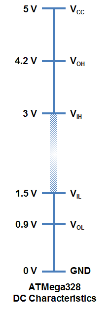
Devices like the raspberry pi and arduino read the digital state by detecting a voltage level above or below a given threshold. By and large, all digital devices use logic levels to determine the state of an input. They also use these logic levels when creating a digital output signal. The threshold voltages allow for clean operation in situations where noise, loss, and other factors would degrade the digital signal. The difference between the high state threshold and low state threshold is referred to as the gap voltage. The larger the gap, the more resilient to noise and loss the logic level is.
One key benefit to using set logic levels is the accurate detection when a threshold is crossed. This is central to using digital inputs as a way to measure analog signals. To do that we use the RC time circuit.
First, lets cover what an analog signal is. Let’s use the room light as example again. Instead of the light being turned on or off with a switch, we now use a dimmer to adjust the brightness of the light. The varying levels of voltage is what makes it an analog signal.
Now back to detecting the analog signal on a digital input. As mentioned, the RC time circuit is used to make this possible. The RC time circuit consists of a variable resistor and a capacitor. The value of the resistor is changed by the analog input. When this occurs, the time it takes for the capacitor to discharge across the resistor changes. Here is the theory behind it.
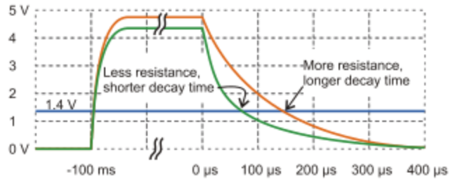
Our digital port is set as an output and it creates a high state. The analog input is setting the value of our resistor. We then change our digital port to an input and begin counting time. Initially, the digital input sees a high because the capacitor still has most of its charge. As we count time, the capacitor begins to discharge across the resistor. The speed of the discharge depends on the resistance of the resistor. At some point, the logic level threshold will be reached when the discharge voltage gets low enough. At that point the digital input will change to a low and our time counting will stop. The time count value is what corresponds with the analog input. I won’t cover how to change the resistor value from an analog input here.
It’s a lot to take in, but it works. Devices that do not have analog inputs benefit greatly from this method. In contrast, devices that allow analog signal inputs use internal circuitry to convert the varying voltage levels to logic levels.
This is called analog to digital conversion, commonly referred to as ADC. ADC chips contain complex circuits that will change varying voltage levels on the input into digital values or bits. The number of bits determines the quality of the readings, also known as resolution. ADC chips with high bit ratings are able to detect finer changes in voltage than those with lower bit ratings. The trade off is it takes more memory to handle higher resolution.
The devices we’ll be using also have analog outputs. They do this digitally by turning an output pin on and off at a very fast rate. Also the rate changes depending on the analog signal it needs to recreate. The process is known as pulse width modulation, more commonly referred to as PWM. Analog circuits typically have a slower response time than digital ones. When a group of digital pulses are sent into an analog circuit, the analog circuit averages out the signal. The result is comparable to the original analog signal.

This process is called signal buffering or conditioning. It makes the signal more representative of the original. This is far from creating an exact copy. To do that would require multiple output pins, more complex circuitry, and would utilize more memory space. PWM and signal conditioning gets the same work done for much less cost and resource usage.
Another form of analog signal processing is level attenuation and amplification. This signal balancing is needed because our devices have set ranges for analog inputs. If we input an analog signal that is weak, our ADC will not capture the quality. If our signal in is too high, we would either clip the signal peaks or damage our devices. Signal balancing is way to get the most out of our ADC. It also isolates the input signal electronically should an unexpected surge occur. These transients can damage our devices if allowed direct contact with them.
That should cover the basics. Next I’ll be covering communications protocols. These are methods used by devices to send data to one another. There are benefits to using them which I’ll cover later. I hope you have enjoyed this post and look forward to seeing you again.