Serial Communications
Ideas and thoughts are shared with people through speech, text, or some other form of communication. This is how one knows, or at least has some idea of, what the other is thinking. Electronic devices are similar. Without communication, devices and people would be isolated in the cosmos. Like language, devices use sets of standards and protocols to accomplish communication.
In this post, I’ll introduce briefly parallel communication. Next I’ll be covering the most fundamental communication methods of serial communication. Communication has dependencies on timing and most of our focus will be on asynchronous communication. Asynchronous communication has several facets like rate, start, stop, and parity. We’ll continue with how these devices are physically linked. Reliability will be a factor so we’ll cover a basic method to meet that challenge. Next, we’ll delve into detail of what the serial data is and how it’s constructed. With that knowledge, we’ll step into the world of UART and why it’s such a common bridgehead. Lastly, I’ll cover common mistakes that should be considered when using serial communication. We’ve got a lot to cover, so lets begin.

Digital electronic devices are binary by nature. This means that the circuitry they contain transfer, process, transmit, and receive are either high voltage states or low voltage states. These voltage states are simply referred to as data.
A single device typically transfers data between its internal circuitry using parallel paths. This isn’t a problem because the nature of an integrated circuit or printed circuit board allow this without much effort.
If we were to add a second device, physically separate from our first devices, linking them together with parallel links becomes a challenge. This is especially true when the distance between the devices becomes great. This is why serial communication was developed.
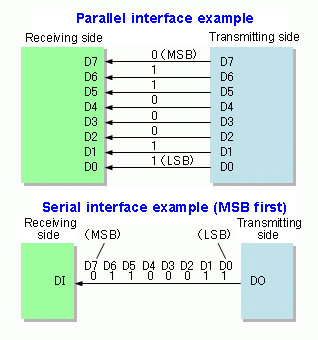
Serial communication is the process were parallel data, or data that contain several voltage states, is assembled into a packet and sent across a single line as a signal. It doesn’t end there. To make the link, the receiving device must take that packet of data and reconstruct the parallel data it contains. The reliability is much greater, however the speed is greatly reduced.
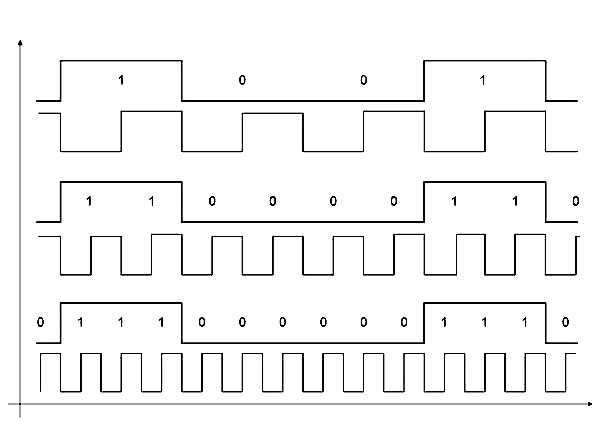
The speed of communication is determined by the clock speed of the serial signal. We use a clock speed because logic states are limited on how fast they can turn on and off. The slower the clock speed, the more reliable the receiver will see that the signal is either high or low. If we set the clock speed too fast, the receiver might not have enough time to accurately determine what the signal is.
Devices that are linked have to agree on what the clock speed is. There are two ways to do this. We can send a clock signal on a separate connection, this is called synchronous serial communication. The other option is to have the devices use internal clocks and set both to a matching rate, this is called asynchronous serial communication.
Synchronous communication adds an additional clock channel requirement to our link. It has some benefits like dopler correction that I won’t go into detail here. Adding the additional channel might not be an option when transmitting over a single fixed media.
Having both devices use an internal clock overcomes the problem of synchronous links. Asynchronous communication lets us set both devices to an agreed data rate without the need for a second clock channel. The data rate is referred to as the baud rate. This is how many bits can be sent in a second, often expressed as bps.
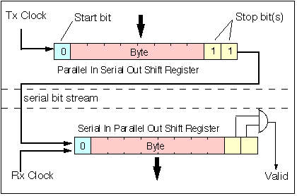
To reliably send the data, the transmitting device assembles the bits into chunk streams or more commonly known as packets. The packets typically consist of 8 bits of data and some quality and control bits to ensure success. The control bits are start and stop indicators for the receiver to accept data. When a transmission occurs, a start bit is sent followed by the data and concluded with a stop bit. The receiving device will see that a stream is about to be sent when the start bit is detected. It buffers the data as it is received and stops when the stop bit is detected. To further ensure quality of the data, a parity bit can be sent so that the receiving device is certain the bits are validated. Parity is done mostly by counting the number if high state bits. As an example, if an 8 bit data packet of 10010111 were received, the parity bit would be 1 since the high state count is an odd value. In contrast a packet of 11010111 would create a parity bit of 0 since the number of 1 bits is even.
The linking of serial communication devices is key. The transmit port of the sending device needs to mate with the receiving port of the device accepting the data. They also need to have an agreed reference, most often this is ground. If the devices will be communicating back an forth, or bidirectionally, then the same linking method applies, transmit to receive.
Devices that have both a transmit and receive port can send and receive data at the same time, this is called full-duplex communication. Some devices have both ports but can only operate one of them at a time, this is called half-duplex.
There are many flavors of serial logic states, I’ll cover the more basic TTL and RS-232 standards. Transistor to Transistor Logic uses lower voltage levels. These are in the range of either 3.3 or 5 VCC. The lower voltage levels allow for faster speed, but are limited by distance. RS-232 uses a higher 13 to -13 volt range. This lets links travel longer distances but speed is limited by the inherent slew rate. The binary logic state for each standard is reversed. This means that a binary 1 state on a TTL bit is typically VCC, whereas the RS-232 logic 1 state is -13 volts. The reverse is true for low binary states. When linking TTL to RS-232, or any other serial logic state, a logic level shifter is needed to match the standards.

When data packets are created the parallel data set of LSB and MSB need to be agreed on. LSB is the least significant bit or the lowest numeric value. MSB is the most significant bit and is the highest numeric value. Lets take this as an example. Say we have a decimal value of 138 and we need to convert this to a binary number of 8 bits, that would be 10001010. Our MSB is 1 which is on the left side and our LSB is 0 on the far right side. When the bits are placed into a packet, they typically are arranged LSB to MSB. This would mean it would look like a mirror of itself, 01010001. It all has to do with how buffers are addressed on the transmitting and receiving devices.
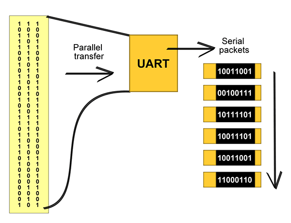
One of the most common methods of packet assembly and buffering is UART. Universal asynchronous receiver and transmitter devices follow a standard on how bits are arranged in a packet. It does the work of taking parallel data and converting it to serial packets. It also converts the serial packets it receives back into data for the parallel data bus. UART has control input and outputs so it can operate a function as needed. UARTs are mostly hardware chips but can also be software, as in the Arduino UART library.
There are common mistakes that can make serial communications a challenge. Sending data from a transmit port to a device transmit port will amount to squat. You’re talking to the mouth, nothing is heard. Baud rate mismatch is another problem. If the transmitting device sends data too fast, the bits will wash over the receiver and garbage will be the result. Another problem is when more than one device transmits on the same data channel or bus. This bus contention will prevent the receiver from getting the data it was intended to get. When it comes to serial data buses, the rule is one bus can accommodate only two devices, the transmitter and the receiver.

Aside from that, serial communications is basically simple. Having the ability to send and receive data between devices that have distances between them can radically improve how electronics can be used. This understanding is going to be needed as we cover this topic again in up comming posts. I hope this has been informative and I look forward to having you back for more topics.