FLIR ESP32-Cam using the Melexis MLX90640
This post will cover how to use the Melexis MLX90640 thermal array sensor with the ESP32-Cam module. The work presented here is based off of the work of others and their documented efforts. The reason for using the ESP32-Cam module is because of its low cost, small form factor, and its built in microSD storage.
The Melexis MLX90640 thermal array sensor can provide a 32 x 24 pixel thermal image in either a 55 or 110 degree field of view along the horizon. It’s a rather expensive sensor, compared to other common micro controller sensors. However, it is much less expensive than higher resolution commercial thermal imaging platforms. The sensor is best suited for stationary placement for measuring settled environments. such as manufacturing or monitoring fixed locations. At the time of this post, the datasheet for this sensor can be found here, (https://www.melexis.com/-/media/files/documents/datasheets/mlx90640-datasheet-melexis.pdf). This post will be using the Pimoroni (https://shop.pimoroni.com/products/mlx90640-thermal-camera-breakout) and Adafruit (https://www.adafruit.com/product/4407) breakout boards in the examples below.
To give some context, it is worthwhile to provide some use case and detail from thermal imaging. The following video demonstrates thermal imaging used in fighting crime, water rescue, and fire fighting. This footage was captured early April, in the Seattle, WA area during midday. For those not familiar with typical weather in this area at that time, the day was likely in the mid 50’s to 60’s, with clear sunny skies heating the roof tops of homes and vehicles. Certain weather conditions or times of year would have a profound affect on the thermal headroom. Keep this in mind later on in this post.
The MLX90640 resolution and detail are very limited compared to the previous example. There are interpolation methods that can be called that will approximate and smooth, which can give the impression of higher quality. The best case scenario that the MLX90640 can achieve natively is a 32 by 24 video at 4 frames per second. Here is a video that demonstrates how an interpolated result would look if it were compared with the earlier video above. It is highlighted in the red box.
It is difficult to call out the details that were captured by the original video. This is the inherent limitation of the MLX90640.
Another significant limitation of the MLX90640 is that it does not generate images or videos natively. The sensor communicates using the I2C protocol and will stream the sensor’s array based on that standard. This required some post processing considerations to be factored in. One benefit of this approach is the overhead is now removed from the ESP32-Cam module and on to the processing platform.
Before continuing on, it should be noted that the following example was based off of code that would either display a live stream of the sensor readings on a LCD or display them through a web interface on a mobile device. Here are links to projects that were leveraged. The intent of this project was to store the data because of its placement. The MLX90640 was going to be used in a way where live monitoring would not be practical or an option, such as on a vehicle or drone.
Szymon Baczyński’s ESP Thermal Camera WebServer
https://github.com/Samox1/ESP_Thermal_Camera_WebServer
SparkFun’s MLX90640 Arduino Example
https://github.com/sparkfun/SparkFun_MLX90640_Arduino_Example
Adafruit’s MLX90640 Example
https://github.com/adafruit/Adafruit_MLX90640
Powering the sensor and ESP32-Cam module was another issue to address. The ESP32-Cam module has lent itself to provide regulated 3.3vdc to sensors in earlier projects. With the MLX90640 datasheet requirements of 25mA, the ESP32-Cam module’s 50mA limit is in par for providing power for the sensor. All that was needed was to provide the ESP32-Cam module with a regulated 5vdc supply.
This is the pin-out to interface the MLX90640 with the ESP32-Cam module, based on the code below.
ESP32-Cam Pin	-	MLX90640 Pin
3.3 Volt	-	Vss
Ground		-	Ground
GPIO 0		-	SCL
GPIO 16	        -	SDA
This was the code base used to gather the I2C data from the MLX90640 and store the results to the microSD media on the ESP32-Cam module. That code base was then compiled in the Arduino IDE and the resulting firmware loaded on the ESP32-Cam module.
/*
Arduino IDE Code
*/


// Declartions and Variables

#include "Arduino.h"
#include "FS.h"                // SD Card ESP32
#include "SD_MMC.h"            // SD Card ESP32

#include <Wire.h>
#define SCL 0  		// Clock Pin for I2C
#define SDA 16			// Data Pin for I2C

#include "MLX90640_API.h"
#include "MLX90640_I2C_Driver.h"

const byte MLX90640_address = 0x33; //Default 7-bit unshifted address of the MLX90640

#define TA_SHIFT 8 //Default shift for MLX90640 in open air

float mlx90640To[768];
paramsMLX90640 mlx90640;

const char* FLIR = "/FLIR_Readings.csv";
String inData;
String flirval;


void HardwareSetup()
{

  Wire.begin(SDA, SCL);
  Wire.setClock(400000); //Increase I2C clock speed to 400kHz

  if (isConnected() == false)
  {
    while (1);
  }

  //Get device parameters - We only have to do this once
  int status;
  uint16_t eeMLX90640[832];
  status = MLX90640_DumpEE(MLX90640_address, eeMLX90640);
  if (status != 0)

  status = MLX90640_ExtractParameters(eeMLX90640, &mlx90640);
  if (status != 0)

  //Once params are extracted, we can release eeMLX90640 array

  MLX90640_SetRefreshRate(MLX90640_address, 0x03); //Set rate to 4Hz
}


//Returns true if the MLX90640 is detected on the I2C bus
boolean isConnected()
{
  Wire.beginTransmission((uint8_t)MLX90640_address);
  if (Wire.endTransmission() != 0)
    return (false); //Sensor did not ACK
  return (true);
}


void FLIRCapture()
{

  long startTime = millis();
  for (byte x = 0 ; x < 2 ; x++)
  {
    uint16_t mlx90640Frame[834];
    int status = MLX90640_GetFrameData(MLX90640_address, mlx90640Frame);

    float vdd = MLX90640_GetVdd(mlx90640Frame, &mlx90640);
    float Ta = MLX90640_GetTa(mlx90640Frame, &mlx90640);

    float tr = Ta - TA_SHIFT; //Reflected temperature based on the sensor ambient temperature
    float emissivity = 0.95;

    MLX90640_CalculateTo(mlx90640Frame, &mlx90640, emissivity, tr, mlx90640To);
  }
  long stopTime = millis();

  for (int x = 0 ; x < 768 ; x++)
  {

    flirval = String(mlx90640To[x], 2);
    inData += flirval;
    inData += ",";

  }

  appendFile(SD_MMC, FLIR, inData.c_str());
  appendFile(SD_MMC, FLIR, "\n");
  inData = ""; // Clear recieved buffer
  flirval = ""; // Clear recieved buffer

}


void StartupMicrSD()
{
   if(!SD_MMC.begin()){
        return;
    }
    uint8_t cardType = SD_MMC.cardType();

    if(cardType == CARD_NONE){
        return;
    }

}


//Append to the end of file in SD card
void appendFile(fs::FS &fs, const char * path, const char * message){

    File file = fs.open(path, FILE_APPEND);
    if(!file){
        return;
    }
    if(file.print(message)){
    } else {
    }
}


void setup()
{

HardwareSetup();
StartupMicrSD();

}


void loop()
{

FLIRCapture();

}
With that firmware loaded and the MLX90640 interfaced, the ESP32-Cam module will create a file on the microSD media named “FLIR_Readings.csv”. This file will contain lines of comma separated values. Each line will contain the entire array stream of 768 readings, 32 x 24. Post-Processing the data file was done with two methods, the first being a bash script, the second being a python routine. Together, these methods will generate image files with interpolation, then generate video files with more interpolation. Here are each of these functions.
#!/bin/bash
# Bash Script ProcessFlir

# https://docs.gimp.org/en/gimp-filter-median-blur.html
# https://legacy.imagemagick.org/Usage/blur/
# https://legacy.imagemagick.org/Usage/blur/#related
# http://ffmpeg.org/ffmpeg-filters.html#minterpolate


counter=1
file=FLIR_Readings.csv
lines=$(cat $file)


for lines in $lines
do

echo "$lines" > raw_${counter}.txt
sed "s/$/\n/; s/,/\n/736; s/,/\n/704; s/,/\n/672; s/,/\n/640; s/,/\n/608; s/,/\n/576; s/,/\n/544; s/,/\n/512; s/,/\n/480; s/,/\n/448; s/,/\n/416; s/,/\n/384; s/,/\n/352; s/,/\n/320; s/,/\n/288; s/,/\n/256; s/,/\n/224; s/,/\n/192; s/,/\n/160; s/,/\n/128; s/,/\n/96; s/,/\n/64; s/,/\n/32; s/,\n//; " raw_${counter}.txt > processed_${counter}.txt
python3 ProcessFLIR.py processed_${counter}.txt
mv processed_${counter}.txt.png processed_${counter}.png
cp processed_${counter}.png processed_original_${counter}.png
convert processed_${counter}.png -median 25 processed_median_${counter}.png
convert processed_median_${counter}.png -blur 0x4 processed_blur_${counter}.png
((counter++))

done


ls -ltr processed_original_*.png > processed_original_.txt
sed -i "s/.*pro */pro/; s/processed_original_/file \'processed_original_/; s/png/png\'/" processed_original_.txt
ffmpeg -y -r 4 -f concat -safe 0 -i "processed_original_.txt" -c:v libx264 -vf "fps=4,format=yuv420p" processed_original_.mov
ffmpeg -y -i processed_original_.mov -filter:v "minterpolate='mi_mode=mci:mc_mode=aobmc:vsbmc=1:fps=16'" processed_original_interpolated.mov

ls -ltr processed_median_*.png > processed_median_.txt
sed -i "s/.*pro */pro/; s/processed_median_/file \'processed_median_/; s/png/png\'/" processed_median_.txt
ffmpeg -y -r 4 -f concat -safe 0 -i "processed_median_.txt" -c:v libx264 -vf "fps=4,format=yuv420p" processed_median_.mov
ffmpeg -y -i processed_median_.mov -filter:v "minterpolate='mi_mode=mci:mc_mode=aobmc:vsbmc=1:fps=16'" processed_median_interpolated.mov

ls -ltr processed_blur_*.png > processed_blur_.txt
sed -i "s/.*pro */pro/; s/processed_blur_/file \'processed_blur_/; s/png/png\'/" processed_blur_.txt
ffmpeg -y -r 4 -f concat -safe 0 -i "processed_blur_.txt" -c:v libx264 -vf "fps=4,format=yuv420p" processed_blur_.mov
ffmpeg -y -i processed_blur_.mov -filter:v "minterpolate='mi_mode=mci:mc_mode=aobmc:vsbmc=1:fps=16'" processed_blur_interpolated.mov

rm raw_*.txt
rm processed_*.txt
# rm *.png


exit
# Python Code
import sys,os
import plotly.express as px


# pathdir='/home/PathContainingData/'
from numpy import genfromtxt
# numpy_array = genfromtxt(pathdir+sys.argv[1], delimiter=',')
numpy_array = genfromtxt(sys.argv[1], delimiter=',')

fig = px.imshow(numpy_array)

fig.update_layout(width=640, height=480, margin=dict(l=0, r=0, b=0, t=0), coloraxis_showscale=False)
fig.update_xaxes(showticklabels=False).update_yaxes(showticklabels=False)
# fig.show()

fig.write_image(sys.argv[1]+".png")


# Command - python3 file.py
# Source - https://plotly.com/python/heatmaps/

# https://plotly.com/python/imshow/
# https://pypi.org/project/plotly-express/
# https://www.cloudacm.com/?p=2674
# https://plotly.com/python/plotly-express/
Here are results from a vehicle application. This video was processed from data captured mid day with the MLX90640 sensor, ESP32-Cam module, and 9v to 5v power supply mounted on the canopy of a vehicle.
The interpolation used in this example has been layered. It merits pointing out each of those layers and how they contributed to improve the overall result. First here is an image of a processed data stream that has no interpolation introduced. It’s pixelated and lacks smooth edges when zoomed in at 20 times.

The next image shows results from median filtering. This interpolation averages a center pixel base on the surrounding pixel values. The smoothing of edges gives the impression of higher detail.

The last image filter applied is a guassian blur. This interpolation averages the surrounding pixel values based on the center pixel value, sort of the reverse of the median blur. This smooths out any remaining edges and blends stark transitions from the median blur.

Those final processed images are then the source for video processing with FFMpeg. The initial video is created at the approximate frame rate that best matches the sensor data rate stored on the microSD media. Then that source video is interpolated at a higher frame rate. Lastly, the video is transposed to reflect that orientation of the sensor with the background.
Adding or tiling additional views can give the observer a better understanding of what is being displayed. This next video has both the 55 and 110 degree field of view MLX9040 sensors, in addition with standard and 120 degree ESP32-Cam visible light sensors. It is important to point out that interpolation was key to the smoothing because all of the sensors are unable to capture at a high frame rate, this is noticeable in some artifacts.
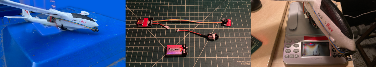
This next video was data captured from a drone. The power source was a standard 9 volt battery which raised concerns about the overall weight. The components were minimalized to only contain the hardware essential for operation. This was especially the case with the voltage regulator by its components being soldered directly to one another. The operational weight of the drone measured at 126 grams, well within flight limits.
Again, it’s difficult even with the interpolation to understand what is being displayed. So this following video is of the same area but with a 720p visible light camera.
Here is the code used to capture visible light camera images with the ESP32-Cam.
/*********
  Rui Santos
  Complete project details at https://RandomNerdTutorials.com/esp32-cam-take-photo-save-microsd-card

  IMPORTANT!!!
   - Select Board "AI Thinker ESP32-CAM"
   - GPIO 0 must be connected to GND to upload a sketch
   - After connecting GPIO 0 to GND, press the ESP32-CAM on-board RESET button to put your board in flashing mode

  Permission is hereby granted, free of charge, to any person obtaining a copy
  of this software and associated documentation files.
  The above copyright notice and this permission notice shall be included in all
  copies or substantial portions of the Software.
*********/

#include "esp_camera.h"
#include "Arduino.h"
#include "FS.h"                // SD Card ESP32
#include "SD_MMC.h"            // SD Card ESP32

// Construct a filename that looks like "/photo_0001.jpg"
long number = 0;

// Pin definition for CAMERA_MODEL_AI_THINKER
#define PWDN_GPIO_NUM     32
#define RESET_GPIO_NUM    -1
#define XCLK_GPIO_NUM      0
#define SIOD_GPIO_NUM     26
#define SIOC_GPIO_NUM     27

#define Y9_GPIO_NUM       35
#define Y8_GPIO_NUM       34
#define Y7_GPIO_NUM       39
#define Y6_GPIO_NUM       36
#define Y5_GPIO_NUM       21
#define Y4_GPIO_NUM       19
#define Y3_GPIO_NUM       18
#define Y2_GPIO_NUM        5
#define VSYNC_GPIO_NUM    25
#define HREF_GPIO_NUM     23
#define PCLK_GPIO_NUM     22


void setup() {


  camera_config_t config;
  config.ledc_channel = LEDC_CHANNEL_0;
  config.ledc_timer = LEDC_TIMER_0;
  config.pin_d0 = Y2_GPIO_NUM;
  config.pin_d1 = Y3_GPIO_NUM;
  config.pin_d2 = Y4_GPIO_NUM;
  config.pin_d3 = Y5_GPIO_NUM;
  config.pin_d4 = Y6_GPIO_NUM;
  config.pin_d5 = Y7_GPIO_NUM;
  config.pin_d6 = Y8_GPIO_NUM;
  config.pin_d7 = Y9_GPIO_NUM;
  config.pin_xclk = XCLK_GPIO_NUM;
  config.pin_pclk = PCLK_GPIO_NUM;
  config.pin_vsync = VSYNC_GPIO_NUM;
  config.pin_href = HREF_GPIO_NUM;
  config.pin_sscb_sda = SIOD_GPIO_NUM;
  config.pin_sscb_scl = SIOC_GPIO_NUM;
  config.pin_pwdn = PWDN_GPIO_NUM;
  config.pin_reset = RESET_GPIO_NUM;
  config.xclk_freq_hz = 20000000;
  config.pixel_format = PIXFORMAT_JPEG;

  if(psramFound()){
    config.frame_size = FRAMESIZE_UXGA; // FRAMESIZE_ + QVGA|CIF|VGA|SVGA|XGA|SXGA|UXGA
    config.jpeg_quality = 10;
    config.fb_count = 2;
  } else {
    config.frame_size = FRAMESIZE_SVGA;
    config.jpeg_quality = 12;
    config.fb_count = 1;
  }

  // Init Camera
  esp_err_t err = esp_camera_init(&config);
  if (err != ESP_OK) {
    return;
  }

  //Serial.println("Starting SD Card");
  if(!SD_MMC.begin()){
    return;
  }

  uint8_t cardType = SD_MMC.cardType();
  if(cardType == CARD_NONE){
    return;
  }

}

void loop() {

  camera_fb_t * fb = NULL;

  // Take Picture with Camera
  fb = esp_camera_fb_get();
  if(!fb) {
    return;
  }

  number++;

  // Construct a filename that looks like "/photo_0001.jpg"

  String filename = "/photo_";
  if(number < 1000) filename += "0";
  if(number < 100)  filename += "0";
  if(number < 10)   filename += "0";
  filename += number;
  filename += ".jpg";

  // Path where new picture will be saved in SD Card
  String path = String(filename);

  fs::FS &fs = SD_MMC;

  File file = fs.open(path.c_str(), FILE_WRITE);
  if(!file){
  }
  else {
    file.write(fb->buf, fb->len); // payload (image), payload length
  }
  file.close();
  esp_camera_fb_return(fb);


  delay(100);
}
The MLX90640 thermal imaging array is an interesting sensor to add to the capabilities of the ESP32-Cam module. The better suited purpose for this setup would be monitoring equipment or settings that require thermal monitoring. It isn’t well suited for mobile applications. However when with normal visual imaging, it could be a viable solution for thermal imaging.