Kauf RGBWW Smart Bulb ESP8266 Firmware
This post will provide some experiences with the Kauf RGBWW Smart Bulb and firmware developed with the Arduino IDE. Details about these bulbs can be found on GitHub, https://github.com/KaufHA/kauf-rgbww-bulbs or from the manufacturer’s website, https://kaufha.com/
I referenced this post about the bulb, https://digiblur.com/2021/09/15/preflashed-esphome-tasmota-smart-bulbs-with-an-added-bonus-kauf-blf10/. It mentions that a new firmware can be uploaded through the device web interface. My attempts to upload firmware compiled in the Arduino IDE were not successful. Initially I thought it was an incorrect OTA flash size setting, but each attempt failed.
One thing that I found odd in my attempts to upload my own firmware was the disruption of wireless service to another ESP01 module nearby. This would happen anytime the bulb was powered on within 2 meters of the ESP01 module. I tried this with another ESP8266 device located in another area and noticed the same issue. The ESP32 modules did not have this problem. This unexpected behavior happened with either of the Kauf BLF10 or BR30 bulbs I had on hand at the time. I’ll come back to this later.
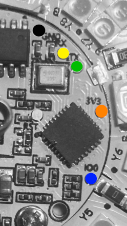
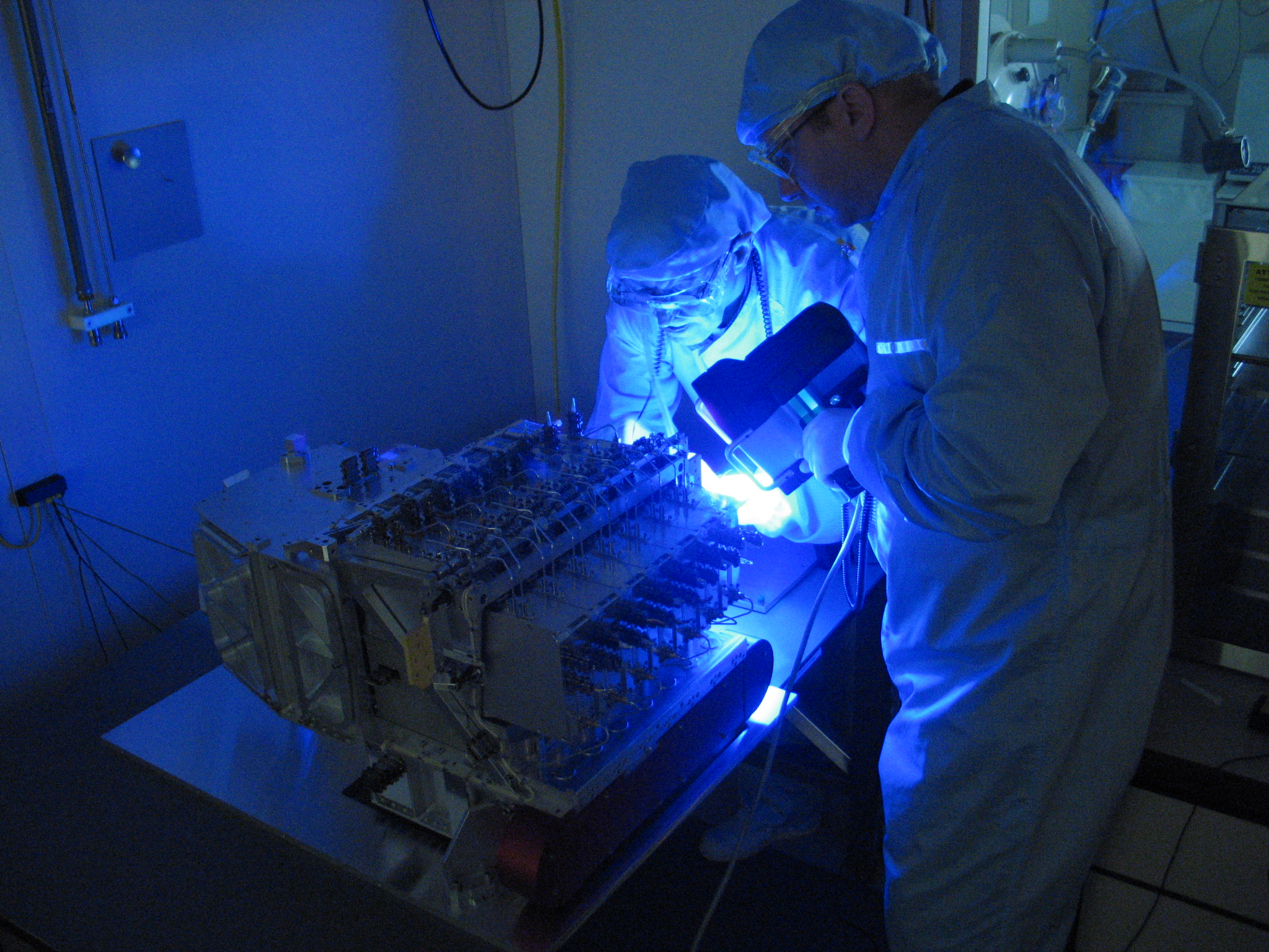
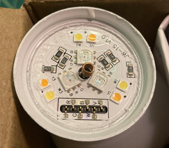
I decided to remove the bulb cover and solder leads on the programming pads to upload my firmware. There are 5 pads that will need to have either a jig or soldered jumpers connected to them. They are GND, RX, TX, 3V3, and IO0. The RX and TX pins are UART receive and transmit pads respectively.
The power supply should be a 3.3 volt source which attaches to pad 3V3 and ground to the GND pad. To get the ESP module in programming mode, the GPIO pin IO0 pad should be held to ground when powering on the bulb through the 3.3 volt source. DO NOT use any AC power source when flashing the ESP module, you risk damaging property or injuring someone. Below is an example of the firmware flashing connections.
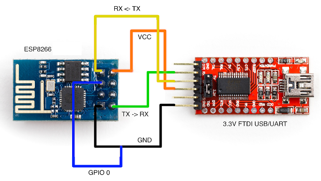
This link provides some guidance on flashing the ESP8266 module, https://www.thissmarthouse.net/howto-flash-firmware-sonoff-t1-switch/. Flashing the ESP module worked fine and the new firmware has functions for me to do OTA updates. After my firmware was loaded, the disruption anomaly was no longer happening, so I suspect the source of the problem isn’t with the hardware.
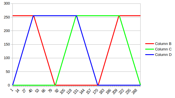
The Kauf LED bulbs included a manual that clearly shows what color LED GPIO pin it uses. The manual is also available online from the GitHub site. This was extremely helpful information to have and saved me time from having to dig for it. The typical rainbow color wheel used to control RGB LED lights follows a 3 phase progression. This link provides details and history of the color wheel, https://en.wikipedia.org/wiki/Color_wheel. Below is a rainbow color band to show how each LED color blends. As the color is changed through the band, the RGB values follow a 3 phase wave pattern. Only one color is at its peak value while either of the two colors change.
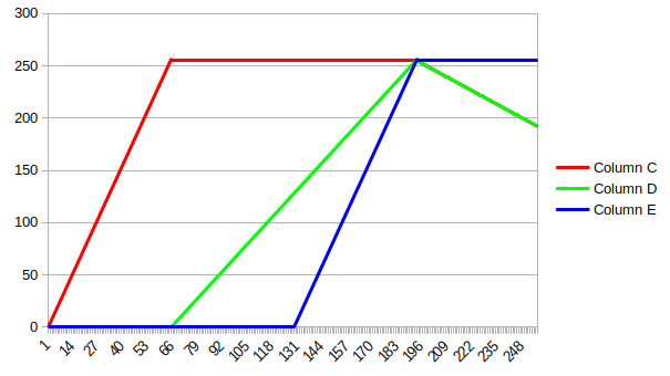
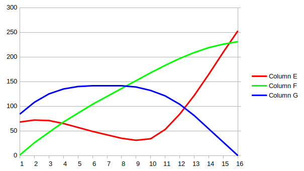
The rainbow color wheel however isn’t a typical use case of LED lighting, color temperature is. The color temperature range can be best compared with a sunrise or sunset, deep reds and oranges fading into dimly lit white and on to deeper blues. The scale is used as a temperature scale of stars measured in kelvins. More about color temperature can be found here, https://en.wikipedia.org/wiki/Color_temperature. Below is an example of a color temperature band. The colors change in a linear progression.
There are other color scales that could be used, here are examples from Plotly, https://plotly.com/javascript/colorscales. There are interesting color sweeps available such as inferno, viridis, or tealrose. Based on the setting they are placed, these color scales could provide a better suited palette that’s more sophisticated than the traditional rainbow or color temperature scales. Some of these scales are purposely set to help those with color blindness, https://en.wikipedia.org/wiki/Color_blindness. Below is an example of a viridis color band. Here the colors change in a curved progression.
Using a RGB LED for inspections isn’t something new and this link provides some guidelines for visual systems, https://www.edn.com/choose-the-right-lighting-for-inspection/. The versitily of the RGB light source for the purpose of object inspection is appealing because it’s adapt to a variety of use cases. However this is likely not the intended use of these bulbs so the reliability should be tested.
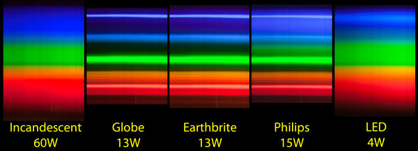
The color spectrum of the Kauf LED bulb offers a wide range because it has five different LED color sources. These are Red, Green, Blue, Warm White, and Cool White. Here’s a site describing the difference between cool and warm lighting, https://www.homeadvisor.com/r/warm-light-vs-cool-light/. It’s ironic that the widely accepted description of warm to cool is the opposite of what their actual color temperature range is, since a temperature of 1900 Kelvin is cooler than 10000 Kelvin. This site provides some comparisons of color spectrum from legacy lighting using spectroscopy, https://smallpond.ca/jim/misc/cfl/
As mentioned earlier, the first batch of out of the box Kauf LED bulbs had a strange effect. When these bulbs were powered on, the neighboring ESP8266 modules would loose their wifi network connection. Powering off the bulbs cleared the issue and the wifi network connections were restored on the ESP8266 modules. Be mindful that these bulbs were fresh out of the box with no configuration on my part. I wanted to investigate this further but had already flashed my firmware on the bulbs, so I ordered additional bulbs in hopes of capturing the RF pattern using my NRF24L01 modules. When the new bulbs arrived, they did not exhibit this effect on neighboring modules.
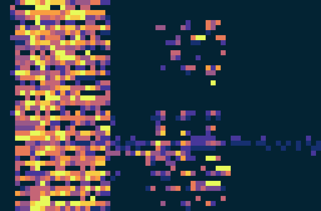
Since the new bulbs had no RF anomaly, I did notice a pattern out of the box with how the LEDs were lit. When powered on for the first time, the blub would flash on then turn red for a bit, then back on. If I turned the bulb off and back on, it would just turn on. Then it was followed by 3 green lights with each successive power cycle. As I power cycled the bulb I began to see a repeatable pattern. Here is a spectrogram of what the bulb colors were. The video contains a window of the spectrogram slit inside a larger window of the same slit stretched to the width of the video.
It was difficult to capture the bulb color directly with a camera due in part to color correction or washout, so this was the reason for using the spectrogram. I’m unsure if the first batch of bulbs behaved this way. I’ll follow up with more spectrograms and RF scans should a different batch arrive with the original wifi disruption issue.
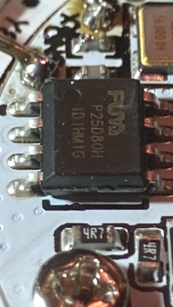
The flash memory on the bulb is a Puya Semiconductor P25D80H with 1MB of storage. I found the datasheet online here, https://datasheet.lcsc.com/lcsc/2006121819_-PUYA–P25D80H-TSH-IT_C559201.pdf. The write cycles in the datasheet were 100,000. This translates to just under 3 years of service if the flash memory performed writes every 15 minutes. It’s probably not the best data logger for anything with a faster refresh rate.
Here is the firmware code used to flash the bulb in the Arduino IDE.
/**

  Header

  Title: ESP8266 HTTP Client Firmware Update with MQTT controlled RGBWW and Saved Settings using Flash Memory
  Version: 1
  Filename: ESP8266-Kauf-RGBWW-Blub_HTTP-Client-Firmware-Update_MQTT_RGBWW-LED_ver1.ino

  Date: 7/27/2023


*/


// Libraries and Declarations

#include <Arduino.h>

#include <ESP8266WiFi.h>

#include <PubSubClient.h>
WiFiClient espClient;
PubSubClient MQTTclient(espClient);
long laststats = 0;
int programflag = 0;
int flashwrite = 0;

#include <ESP8266HTTPClient.h>
#include <ESP8266httpUpdate.h>


// NTP Libraries, Declarations, and Variables
#include <NTPClient.h>
#include <WiFiUdp.h>
WiFiUDP ntpUDP;
NTPClient timeClient(ntpUDP, "pool.ntp.org");
//Week Days
String weekDays[7]={"Sunday", "Monday", "Tuesday", "Wednesday", "Thursday", "Friday", "Saturday"};
//Month names
String months[12]={"January", "February", "March", "April", "May", "June", "July", "August", "September", "October", "November", "December"};


// include library to read and write from flash memory
#include <EEPROM.h>

// define the number of bytes you want to access
#define EEPROM_SIZE 1

// Variables

// MQTT Broker
const char* mqtt_server = "mqtt-broker-ip-address";     // Put your MQTT Broker here

// Your WiFi credentials
const char* ssid =     "wifi-ssid";               // Put your SSID here
const char* password = "wifi-psk";                // Put your PASSWORD here

//Your Domain name with URL path or IP address with path
const char* firmware_server = "http://node-red-ip-address:1880/get-firmware-path";

// Global variables
int totalLength;       //total size of firmware
int currentLength = 0; //current size of written firmware

unsigned long lasttimeupdate = 0; // Time counter for periodic NTP time checks
unsigned long lasttimereboot = 0; // Time counter for periodic reboots to avoid millis rollover

String FirmwarePath;

ADC_MODE(ADC_VCC);  // See comment block below for more details
/*
  see - http://arduino.esp8266.com/Arduino/versions/2.0.0-rc2/doc/libraries.html

  ESP.getVcc() may be used to measure supply voltage. ESP needs to reconfigure the ADC at
  startup in order for this feature to be available. Add the following line to the top of
  your sketch to use getVcc:

  ADC_MODE(ADC_VCC);

  TOUT pin has to be disconnected in this mode.

  Note that by default ADC is configured to read from TOUT pin using analogRead(A0), and
  ESP.getVCC() is not available.

 */


int RedLED = 4;          // Red LED connected to digital pin 4
int GreenLED = 12;       // Green LED connected to digital pin 12
int BlueLED = 14;        // Blue LED connected to digital pin 14
int ColdWhiteLED = 5;    // Cold White LED connected to digital pin 5
int WarmWhiteLED = 13;   // Warm White LED connected to digital pin 13


// MQTT Functions

void callback(char* topic, byte* message, unsigned int length) {

  String messageTemp;

  for (int i = 0; i < length; i++) {
    messageTemp += (char)message[i];
  }

  if (String(topic) == "ESP8266-Kauf-RGBWW-Blub/CommitFlash") {
    if(messageTemp == "WriteFlash"){
      EEPROM.write(0, flashwrite);
      EEPROM.commit();
    }
  }

  if (String(topic) == "ESP8266-Kauf-RGBWW-Blub/HTTP-Get") {
    if(messageTemp == "CheckFirmware"){
      FirmwarePath = httpGETRequest(firmware_server);
    }
  }

  if (String(topic) == "ESP8266-Kauf-RGBWW-Blub/HTTP-Get") {
    if(messageTemp == "UpdateFirmware"){
      FirmwarePath = httpGETRequest(firmware_server);
      t_httpUpdate_return ret = ESPhttpUpdate.update(espClient, FirmwarePath);
    }
  }

  if (String(topic) == "ESP8266-Kauf-RGBWW-Blub/UpdateTime") {
    if(messageTemp == "CheckTime"){
          timeClient.update();
    }
  }

  if (String(topic) == "ESP8266-Kauf-RGBWW-Blub/Reboot") {
    if(messageTemp == "Reboot"){
      ESP.restart();
    }
  }

  if (String(topic) == "ESP8266-Kauf-RGBWW-Blub/RedLED") {
   int intTemp = messageTemp.toInt();
   analogWrite(RedLED, intTemp);
  }

  if (String(topic) == "ESP8266-Kauf-RGBWW-Blub/GreenLED") {
   int intTemp = messageTemp.toInt();
   analogWrite(GreenLED, intTemp);
  }

  if (String(topic) == "ESP8266-Kauf-RGBWW-Blub/BlueLED") {
   int intTemp = messageTemp.toInt();
   analogWrite(BlueLED, intTemp);
  }

  if (String(topic) == "ESP8266-Kauf-RGBWW-Blub/ColdWhiteLED") {
   int intTemp = messageTemp.toInt();
   analogWrite(ColdWhiteLED, intTemp);
  }

  if (String(topic) == "ESP8266-Kauf-RGBWW-Blub/WarmWhiteLED") {
   int intTemp = messageTemp.toInt();
   flashwrite = intTemp;
   analogWrite(WarmWhiteLED, intTemp);
  }

  if (String(topic) == "ESP8266-Kauf-RGBWW-Blub/ColorTemp") {
   int intTemp = messageTemp.toInt();
   if ( intTemp <= 64 ) {
      analogWrite(RedLED, intTemp*4);
      analogWrite(GreenLED, 0);
      analogWrite(BlueLED, 0);
   }
   if ( intTemp > 64 && intTemp < 129 ) {
      analogWrite(RedLED, 255);
      analogWrite(GreenLED, (intTemp-64)*2);
      analogWrite(BlueLED, 0);
   }
   if ( intTemp > 128 && intTemp < 193 ) {
      analogWrite(RedLED, 255);
      analogWrite(GreenLED, (intTemp-64)*2);
      analogWrite(BlueLED, (intTemp-128)*4);
   }
   if ( intTemp > 192 && intTemp < 256 ) {
      analogWrite(RedLED, 255-(intTemp-192));
      analogWrite(GreenLED, 255-(intTemp-192));
      analogWrite(BlueLED, 255);
   }
  }

}


void reconnect() {
  // Loop until we're reconnected
  while (!MQTTclient.connected()) {
    // Attempt to connect
    if (MQTTclient.connect("ESP8266-Kauf-RGBWW-Blub")) {
      // Subscribe
      // Do you not subscribe to my methods?
      // ESP8266-Kauf-RGBWW-Blub/# for everything, or ESP8266-Kauf-RGBWW-Blub/Uptime for just the Uptime
      MQTTclient.subscribe("ESP8266-Kauf-RGBWW-Blub/#");
    } else {
      // Wait 5 seconds before retrying
      delay(5000);
    }
  }
}


// HTTP Get Functions
String httpGETRequest(const char* firmware_server) {
  HTTPClient http;

  // Your Domain name with URL path or IP address with path
  http.begin(espClient, firmware_server);

  // Send HTTP POST request
  int httpResponseCode = http.GET();

  String payload = "{}";

  if (httpResponseCode>0) {
    payload = http.getString();
  }
  // Free resources
  http.end();

  return payload;
}


void UpdateStats() {

  long stats = millis();
  if (stats - laststats > 5000) {
    laststats = stats;

    MQTTclient.publish("ESP8266-Kauf-RGBWW-Blub/Firmware", "ESP8266-Kauf-RGBWW-Blub_HTTP-Client-Firmware-Update_MQTT_RGBWW-LED_ver1");
    String StringUptime = String(millis());
    MQTTclient.publish("ESP8266-Kauf-RGBWW-Blub/Uptime", StringUptime.c_str());
    String StringHWAddress = String(WiFi.macAddress());
    MQTTclient.publish("ESP8266-Kauf-RGBWW-Blub/HWAddress", StringHWAddress.c_str());
    String StringWifiSignal = String(WiFi.RSSI());
    MQTTclient.publish("ESP8266-Kauf-RGBWW-Blub/WifiSignal",StringWifiSignal.c_str());

    String StringFreeHeapSize = String(ESP.getFreeHeap());
    MQTTclient.publish("ESP8266-Kauf-RGBWW-Blub/FreeHeapSize",StringFreeHeapSize.c_str());
    String StringHeapFragmentation = String(ESP.getHeapFragmentation());
    MQTTclient.publish("ESP8266-Kauf-RGBWW-Blub/HeapFragmentation",StringHeapFragmentation.c_str());
    String StringMaxFreeBlockSize = String(ESP.getMaxFreeBlockSize());
    MQTTclient.publish("ESP8266-Kauf-RGBWW-Blub/MaxFreeBlockSize",StringMaxFreeBlockSize.c_str());
    String StringSketchSize = String(ESP.getSketchSize());
    MQTTclient.publish("ESP8266-Kauf-RGBWW-Blub/SketchSize",StringSketchSize.c_str());
    String StringFreeSketchSpace = String(ESP.getFreeSketchSpace());
    MQTTclient.publish("ESP8266-Kauf-RGBWW-Blub/FreeSketchSpace",StringFreeSketchSpace.c_str());
    String StringCpuFreqMHz = String(ESP.getCpuFreqMHz());
    MQTTclient.publish("ESP8266-Kauf-RGBWW-Blub/CpuFreqMHz",StringCpuFreqMHz.c_str());
    String StringChipId = String(ESP.getChipId());
    MQTTclient.publish("ESP8266-Kauf-RGBWW-Blub/ChipId",StringChipId.c_str());
    String StringVcc = String(ESP.getVcc());
    MQTTclient.publish("ESP8266-Kauf-RGBWW-Blub/Vcc",StringVcc.c_str());

    //Get a Time Structure
    String formattedTime = timeClient.getFormattedTime();
    String StringformattedTime = String(formattedTime);
    MQTTclient.publish("ESP8266-Kauf-RGBWW-Blub/Time",StringformattedTime.c_str());

    //Get a Date Structure
    time_t epochTime = timeClient.getEpochTime();
    struct tm *ptm = gmtime ((time_t *)&epochTime);
    int monthDay = ptm->tm_mday;
    int currentMonth = ptm->tm_mon+1;
    String currentMonthName = months[currentMonth-1];
    int currentYear = ptm->tm_year+1900;

    //Publish complete date:
    String StringcurrentDate = String(currentMonth) + "/" + String(monthDay) + "/" + String(currentYear);
    MQTTclient.publish("ESP8266-Kauf-RGBWW-Blub/Date",StringcurrentDate.c_str());

    //Publish Epoch:
    String StringEpochTime = String(timeClient.getEpochTime());
    MQTTclient.publish("ESP8266-Kauf-RGBWW-Blub/EpochTime",StringEpochTime.c_str());


    // String StringFirmwarePath = String(FirmwarePath);
    MQTTclient.publish("ESP8266-Kauf-RGBWW-Blub/FirmwarePath",FirmwarePath.c_str());
  }

}


// Setup Function
void setup() {

  EEPROM.begin(EEPROM_SIZE);
  int intTemp = EEPROM.read(0);
  analogWrite(WarmWhiteLED, intTemp);

  delay(1000);

  WiFi.mode(WIFI_STA);
  WiFi.begin(ssid, password);
  while (WiFi.status() != WL_CONNECTED)
    {
      // Just wait it out
      delay(250);
    }

  MQTTclient.setServer(mqtt_server, 1883);
  MQTTclient.setCallback(callback);

  ESPhttpUpdate.setClientTimeout(2000);  // default was 8000

  timeClient.begin(); // Initialize a NTPClient to get time
  timeClient.setTimeOffset(-25200);
  // Set offset time in seconds to adjust for your timezone, for example:
  // GMT -7 = -25200 (see - https://time.gov/)
  delay(1000);
  timeClient.update();

}


// Main Loop Function
void loop() {

  if (!MQTTclient.connected()) {
    reconnect();
  }
  MQTTclient.loop();
  UpdateStats();

  // Update time from NTP source every 1 day (24 * 60 * 60 * 1000 = 86400000 milli-seconds)
  unsigned long timeupdate = millis();
  if (timeupdate - lasttimeupdate > 86400000) {
    lasttimeupdate = timeupdate;
    timeClient.update();
  }

  // Reboot microcontroller every 30 day to avoid millis() rollover (30 * 24 * 60 * 60 * 1000 = 2592000000 milli-seconds)
  unsigned long timereboot = millis();
  if (timereboot - lasttimereboot > 2592000000) {
      // Reboot command
      ESP.restart();
  }


}


/**

  Footer

*/
Here are the key features of this firmware build.
- WiFi client to existing network
- MQTT client for publishing and subscribing from a broker
- NTP client timestamp for local time zone
- RGBWW values can be stored to flash and are referenced on reboot
- Firmware updates can be initiated through Node-Red
- Color temperature scale for RGB LEDs
- Scheduled reboot to avoid rollover of millis() function
Node-Red is the front end interface to the bulb. It displays stats that the bulb provides at a set interval. Node-Red also monitors and reports the response from the bulb. There are controls in Node-Red to restart the bulb, check for current time, set or write RGBWW levels to flash memory, and perform firmware updates.

Node-Red is used to control the bulb light levels based on scheduling. In the following example, Node-Red mimics the behavior of a sunsrise by fading the bulb on through the color temperature scale. I’ve done this with a RGBW LED strip in this post, https://www.cloudacm.com/?p=4290
- Inject Node – Repeat at a set time on set days with a defined payload
- Looptimer Node – Loops every 5 seconds for a max of 135 loops, times out after 700 seconds
- Function Node – Adds 1 step to the ColorTemp variable with each loop
var ColorTemp = context.get("counter") || 0;
ColorTemp = (ColorTemp+1);
if(ColorTemp == 136){
msg.payload = ColorTemp;
context.set("counter", 0);
return msg;
}
msg.payload = ColorTemp;
context.set("counter", ColorTemp);
return msg;
- Function Node – Sets the ColorTemp variable to 0 at end of loop
- Function Node – Sets the WarmTemp variable to a set value at end of loop
- MQTT Out Node – Publishes ColorTemp variable from any of the ColorTemp Function Nodes
- MQTT Out Node – Publishes WarmTemp variable from the WarmTemp Function Node
The BLF10 and BR30 Kauf RGBWW Smart Bulbs aren’t too difficult to open and flash. However I did have trouble with the A15 bulbs. I had assumed that the flashing pads would be accessible but found that the LED PCB was layered on top of the ESP8266 PCB.
Removing the base of the bulb revealed that the hot lead was crimped to the base housing and the converter was wrapped with a single layer of thin tape. Accessing the flash pins would require butchering the upper plastic housing.
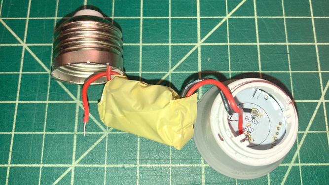
This was an unfortunate discovery. If there is a way for me to install my firmware using the stock Kauf OTA firmware, then I might consider using this bulb as well.
All in all, these are interesting devices with the ability to do more than just light a room.