A Scope In A Pinch
When working with device electronics, it’s important to work within voltage and signal limits. Designing circuits that interact with those devices need to have expected results. There can be several stages in a circuit design where voltages or signals are changed. It can be extremely challenging to design without some kind of measurement at each stage. Having a tool that can measure multiple stages at the same time in realtime is key. Fortunately, this can be done for little cost using a micro-controller with a serial connection to the Arduino IDE.
This post will cover the use and customization of the Serial Plotter available in the Arduino IDE Tools menu. This post is based off of the following link that introduces its use, https://www.makerguides.com/how-to-visualise-data-on-the-arduino-serial-plotter/. The plotter was added to the Arduino IDE in version 1.6.6 (2015.11.03), based on the release notes https://www.arduino.cc/en/software/ReleaseNotes. However, several updates have been made since and more are likely to be introduced.
The Serial Plotter configuration file is theme.txt, which is located under the lib\theme directories. The “GUI – PLOTTING” section in that file contains the following lines in the examples used below.
# GUI - PLOTTING
# Comments - multiple color output of signals

# Black Background
plotting.bgcolor = #000000

plotting.color = #c0c0c0
plotting.gridcolor = #808080
plotting.boundscolor = #c0c0c0

# Limit to 7 signals to be plotted
plotting.graphcolor.size = 7

# Colors for each signal line to be plotted
# - uses #rrggbb hex values
plotting.graphcolor.00 = #bb44bb
plotting.graphcolor.01 = #ff4444
plotting.graphcolor.02 = #ff8800
plotting.graphcolor.03 = #bbbb00
plotting.graphcolor.04 = #00bb00
plotting.graphcolor.05 = #00bbbb
plotting.graphcolor.06 = #0044ff
The following plot shows an example of various signals with these theme settings.
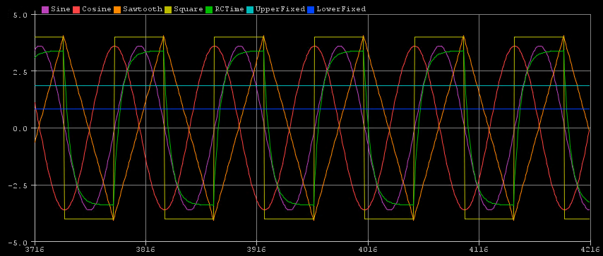
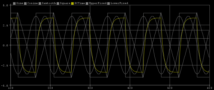
Any changes made to the theme.txt file require that the IDE be restarted to take effect. In the next example, the colors have been changed so that attention is focused on the signal of interest.
This is the code used for these examples, which runs on an Arduino UNO.
float Sawtooth = -4.05;
float SWFactor = .18;
float Sinewave;
float Squarewave = 0;
float SquarewaveValue = 4;
float RCTime = .1;
float RCTimeFactor = .6;
float RCTimeMultiplier = .85;
float UpperFixed = 1.85;
float LowerFixed = .85;
long DelayTime = 50;

void setup(void)
{
  Serial.begin(115200);
  while (!Serial) {
      delay(1);
  }

  Serial.print("Sine,");
  Serial.print("Cosine,");
  Serial.print("Sawtooth,");
  Serial.print("Square,");
  Serial.print("RCTime,");
  Serial.print("UpperFixed,");
  Serial.print("LowerFixed");
  Serial.println("");


}

void loop(void)
{

for (Sinewave = 0; Sinewave < 180; Sinewave=Sinewave + 4) {

Serial.print(3.6*sin(Sinewave * (PI / 180)));
Serial.print(",");
Serial.print(3.6*cos(Sinewave * (PI / 180)));
Serial.print(",");
Sawtooth = Sawtooth + SWFactor;
Serial.print(Sawtooth);
Serial.print(",");
Squarewave = SquarewaveValue;
Serial.print(Squarewave);
Serial.print(",");
RCTime = (RCTime + RCTimeFactor)* RCTimeMultiplier;
Serial.print(RCTime);
Serial.print(",");
Serial.print(UpperFixed);
Serial.print(",");
Serial.println(LowerFixed);
delay (DelayTime);
}

for (Sinewave = 180; Sinewave < 360; Sinewave=Sinewave + 4) {

Serial.print(3.6*sin(Sinewave * (PI / 180)));
Serial.print(",");
Serial.print(3.6*cos(Sinewave * (PI / 180)));
Serial.print(",");
Sawtooth = Sawtooth - SWFactor;
Serial.print(Sawtooth);
Serial.print(",");
Squarewave = -(SquarewaveValue);
Serial.print(Squarewave);
Serial.print(",");
RCTime = (RCTime - RCTimeFactor)* RCTimeMultiplier;
Serial.print(RCTime);
Serial.print(",");
Serial.print(UpperFixed);
Serial.print(",");
Serial.println(LowerFixed);
delay (DelayTime);
}


}
Using the Serial Plotter tool is a simple and quick way to visualize circuit signals and levels. This is another example which uses Processing to provide more sophisticated plots, https://github.com/devinaconley/arduino-plotter. The features in the Arduino IDE are likely to change, so check the release notes if this interest you.