Wemos 433 Mhz RF Receiver
I’ve been using RTL_433 with a SDR for a few years now with modest success. This setup will detect and identify a variety of 433Mhz sensor readings. The output is piped to a MQTT broker and from there the readings are presented graphically.
At first this was done on a Raspberry Pi running a bash script on startup, with the following one liner command.
rtl_433 -F json | mosquitto_pub -h <MQTT-Broker> -i RTL_433 -l -t RTL_433/SDR_FEED
Unpredictably, problems would arise when the process would hang and readings no longer were being received. This was addressed by placing the process under a supervisor task, details can be found in this post titled “Scheduled vs Supervised Tasks” https://www.cloudacm.com/?p=3956. Another issue discovered was that some sensors failed to be detected by the SDR. The standard antenna included with the SDR was replaced with a 433 Mhz tuned antenna, https://www.amazon.com/Zerone-433MHZ-Antenna-Signal-Amplifier/dp/B07DMXSX45. This improved coverage, but there were still some PIR sensors that were in dead spots. It was becoming clearer that the SDR had a hard limit and to get these dead spot sensors online, I would have to place some kind of bridging device closer to them.
I had seen demonstrations of 433 Mhz RF modules being used with microcontrollers in this post, https://randomnerdtutorials.com/decode-and-send-433-mhz-rf-signals-with-arduino/. However, many of the demonstrations I found online used the RF modules as a wireless link between two microcontrollers. I had a Sonoff RF bridge available and looked into using it for the purpose of receiving and processing sensors. However, that would require hardware modifications and following a rather lengthy setup process with a narrow range of supported sensors.
Along the way there were GitHub repos that caught my attention, https://github.com/sui77/rc-switch/ and https://github.com/ninjablocks/433Utils. It was this blog by Ray Wang that spelled out clearly what I was intending to do, https://rayshobby.net/reverse-engineer-wireless-temperature-humidity-rain-sensors-part-1/. This was further elaborated by Brad Hunting’s GitHub repo, https://github.com/bhunting/Acurite_00592TX_sniffer. From here out the pieces started to fall into place as I found more details on Brad’s blog, https://www.techspin.info/.
One of the key steps in getting the microcontroller to detect and decode the RF sensors was identifying the pattern. I used a logic analyzer to get the timings and sequences. From there I was able to display the sensor data with the microcontroller. This worked for my PIR motion sensors, temp/humidity sensors, door reed switch sensors, and key fob controllers.
I had some problems porting the code to work on the Wemos ESP8266. The code worked fine on the Arduino Uno, but the interrupts are handled differently on the ESP8266 microcontroller. The function called by attachInterrupt had to have ICACHE_RAM_ATTR defined. This video briefly explains some of the interrupt dependencies of the platform.
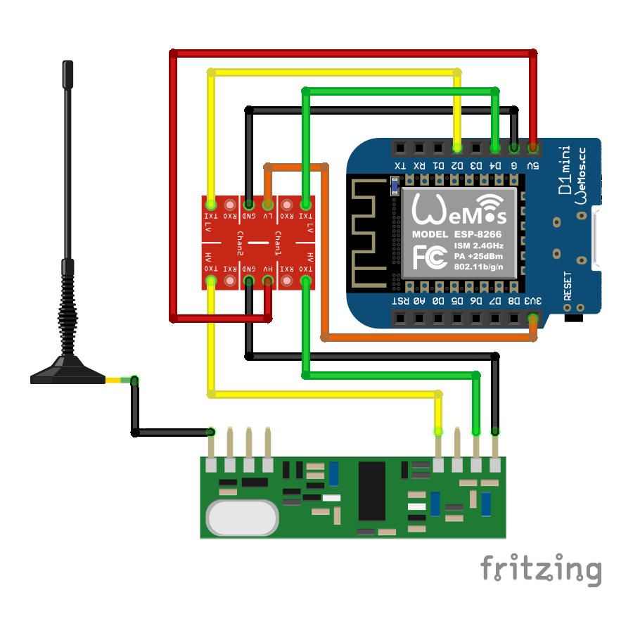
Another problem I had was with the 433 Mhz receiver hardware. It operates at 5 volts and was causing a brownout of the Wemos when the microcontroller was attempting to boot. A workaround for this was to control the power to the receiver from the Wemos using a logic level shifter. The level shifter was already in use to shift the 5 volt signal from the receiver to 3.3 volts on the Wemos. Using a level shifter as a power supply is not recommended, but the low current draw of the receiver allowed it just this time. Here is the wiring of the components.
 Since this project was to detect dead spot PIR sensors, this is the code that was loaded on the Wemos. I liked that the library dependencies were minimal which made integrating functions from earlier code easier.
/*

  Header

  Title: Wemos ESP8266 433Mhz RF PIR MQTT Bridge
  Version: 2
  Filename: Wemos-433_MQTT_PIR-Sensor_Display_ver2.ino

  Date: 12/10/2023

  Author: Patrick Gilfeather - CloudACM
  https://www.cloudacm.com

  Base Code based on
  Convert RF signal into bits (PIR Sensor)
  Written by : Ray Wang (Rayshobby LLC)
  http://rayshobby.net/?p=8998

  For ESP8266-Wemos, use LOLIN(WEMOS) D1, R2, and mini


*/


// Libraries and Declarations
#include <Arduino.h>

#include <ESP8266WiFi.h>

#include <PubSubClient.h>
WiFiClient espClient;
PubSubClient MQTTclient(espClient);
long laststats = 0;
int programflag = 0;


// NTP Libraries, Declarations, and Variables
#include <NTPClient.h>
#include <WiFiUdp.h>
WiFiUDP ntpUDP;
NTPClient timeClient(ntpUDP, "pool.ntp.org");
//Week Days
String weekDays[7]={"Sunday", "Monday", "Tuesday", "Wednesday", "Thursday", "Friday", "Saturday"};
//Month names
String months[12]={"January", "February", "March", "April", "May", "June", "July", "August", "September", "October", "November", "December"};


// Variables

// MQTT Broker
const char* mqtt_server = "#########";     // Put your MQTT Broker here

// Your WiFi credentials
const char* ssid =     "#########";               // Put your SSID here
const char* password = "#########";           // Put your PASSWORD here

unsigned long lasttimeupdate = 0; // Time counter for periodic NTP time checks
unsigned long lasttimereboot = 0; // Time counter for periodic reboots to avoid millis rollover

ADC_MODE(ADC_VCC);  // See comment block below for more details
/*
  see - http://arduino.esp8266.com/Arduino/versions/2.0.0-rc2/doc/libraries.html

  ESP.getVcc() may be used to measure supply voltage. ESP needs to reconfigure the ADC at
  startup in order for this feature to be available. Add the following line to the top of
  your sketch to use getVcc:

  ADC_MODE(ADC_VCC);

  TOUT pin has to be disconnected in this mode.

  Note that by default ADC is configured to read from TOUT pin using analogRead(A0), and
  ESP.getVCC() is not available.

 */

// ring buffer size has to be large enough to fit
// data between two successive sync signals
#define RING_BUFFER_SIZE  256

#define SYNC_LENGTH 12200
#define SYNC_RANGE  300  // Was hard coded to 400 but too much crosstalk

#define BIT1_HIGH  1200
#define BIT1_LOW   400
#define BIT0_HIGH  400
#define BIT0_LOW   1200
#define BIT_RANGE  100

#define DATAPIN  2  // D2 is interrupt 1
#define CONTROLPIN  4  // D4 is used to control power to the 433Mhz reciever module
#define DELAYTIME 50  // 50 ms delay commonly used throughout code

unsigned long timings[RING_BUFFER_SIZE];
unsigned int syncIndex1 = 0;  // index of the first sync signal
unsigned int syncIndex2 = 0;  // index of the second sync signal
bool received = false;


// detect if a sync signal is present
bool isSync(unsigned int idx) {
  // check if we've received 4 squarewaves of matching timing
  int i;

  // check if there is a long sync period prior to the 4 squarewaves
  unsigned long t = timings[(idx+RING_BUFFER_SIZE-i)%RING_BUFFER_SIZE];
  // if(t<(SYNC_LENGTH-400) || t>(SYNC_LENGTH+400) ||
  if(t<(SYNC_LENGTH-SYNC_RANGE) || t>(SYNC_LENGTH+SYNC_RANGE) ||
    digitalRead(DATAPIN) != HIGH) {
    return false;
  }
  return true;
}


/* Interrupt 1 handler */
void ICACHE_RAM_ATTR handler() {
  static unsigned long duration = 0;
  static unsigned long lastTime = 0;
  static unsigned int ringIndex = 0;
  static unsigned int syncCount = 0;

  // ignore if we haven't processed the previous received signal
  if (received == true) {
    return;
  }
  // calculating timing since last change
  long time = micros();
  duration = time - lastTime;
  lastTime = time;

  // store data in ring buffer
  ringIndex = (ringIndex + 1) % RING_BUFFER_SIZE;
  timings[ringIndex] = duration;

  // detect sync signal
  if (isSync(ringIndex)) {
    syncCount ++;
    // first time sync is seen, record buffer index
    if (syncCount == 1) {
      syncIndex1 = (ringIndex+1) % RING_BUFFER_SIZE;
    }
    else if (syncCount == 2) {
      // second time sync is seen, start bit conversion
      syncCount = 0;
      syncIndex2 = (ringIndex+1) % RING_BUFFER_SIZE;
      unsigned int changeCount = (syncIndex2 < syncIndex1) ? (syncIndex2+RING_BUFFER_SIZE - syncIndex1) : (syncIndex2 - syncIndex1);
      // changeCount must be 50 -- 24 bits x 2 + 2 for sync
      if (changeCount != 50) {
        received = false;
        syncIndex1 = 0;
        syncIndex2 = 0;
      }
      else {
        received = true;
      }
    }

  }
}


// MQTT Functions

void callback(char* topic, byte* message, unsigned int length) {

  String messageTemp;

  for (int i = 0; i < length; i++) {
    messageTemp += (char)message[i];
  }

  if (String(topic) == "Wemos-433/UpdateTime") {
    if(messageTemp == "CheckTime"){
          timeClient.update();
    }
  }

  if (String(topic) == "Wemos-433/Reboot") {
    if(messageTemp == "Reboot"){
      ESP.restart();
    }
  }

}


void reconnect() {
  // Loop until we're reconnected
  while (!MQTTclient.connected()) {
    // Attempt to connect
    if (MQTTclient.connect("Wemos-433")) {
      // Subscribe
      // Do you not subscribe to my methods?
      // Wemos-433/# for everything, or Wemos-433/Uptime for just the Uptime
      MQTTclient.subscribe("Wemos-433/#");
    } else {
      // Wait 5 seconds before retrying
      delay(5000);
    }
  }
}


void UpdateStats() {

  long stats = millis();
  if (stats - laststats > 5000) {
    laststats = stats;

    MQTTclient.publish("Wemos-433/Firmware", "Wemos-433_MQTT_PIR-Sensor_Display_ver2");
    String StringUptime = String(millis());
    MQTTclient.publish("Wemos-433/Uptime", StringUptime.c_str());
    String StringHWAddress = String(WiFi.macAddress());
    MQTTclient.publish("Wemos-433/HWAddress", StringHWAddress.c_str());
    String StringWifiSignal = String(WiFi.RSSI());
    MQTTclient.publish("Wemos-433/WifiSignal",StringWifiSignal.c_str());

    String StringFreeHeapSize = String(ESP.getFreeHeap());
    MQTTclient.publish("Wemos-433/FreeHeapSize",StringFreeHeapSize.c_str());
    String StringHeapFragmentation = String(ESP.getHeapFragmentation());
    MQTTclient.publish("Wemos-433/HeapFragmentation",StringHeapFragmentation.c_str());
    String StringMaxFreeBlockSize = String(ESP.getMaxFreeBlockSize());
    MQTTclient.publish("Wemos-433/MaxFreeBlockSize",StringMaxFreeBlockSize.c_str());
    String StringSketchSize = String(ESP.getSketchSize());
    MQTTclient.publish("Wemos-433/SketchSize",StringSketchSize.c_str());
    String StringFreeSketchSpace = String(ESP.getFreeSketchSpace());
    MQTTclient.publish("Wemos-433/FreeSketchSpace",StringFreeSketchSpace.c_str());
    String StringCpuFreqMHz = String(ESP.getCpuFreqMHz());
    MQTTclient.publish("Wemos-433/CpuFreqMHz",StringCpuFreqMHz.c_str());
    String StringChipId = String(ESP.getChipId());
    MQTTclient.publish("Wemos-433/ChipId",StringChipId.c_str());
    String StringVcc = String(ESP.getVcc());
    MQTTclient.publish("Wemos-433/Vcc",StringVcc.c_str());

    //Get a Time Structure
    String formattedTime = timeClient.getFormattedTime();
    String StringformattedTime = String(formattedTime);
    MQTTclient.publish("Wemos-433/Time",StringformattedTime.c_str());

    //Get a Date Structure
    time_t epochTime = timeClient.getEpochTime();
    struct tm *ptm = gmtime ((time_t *)&epochTime);
    int monthDay = ptm->tm_mday;
    int currentMonth = ptm->tm_mon+1;
    String currentMonthName = months[currentMonth-1];
    int currentYear = ptm->tm_year+1900;

    //Publish complete date:
    String StringcurrentDate = String(currentMonth) + "/" + String(monthDay) + "/" + String(currentYear);
    MQTTclient.publish("Wemos-433/Date",StringcurrentDate.c_str());

    //Publish Epoch:
    String StringEpochTime = String(timeClient.getEpochTime());
    MQTTclient.publish("Wemos-433/EpochTime",StringEpochTime.c_str());

  }

}


void setup() {
  delay(DELAYTIME);

  pinMode(CONTROLPIN, OUTPUT);
  digitalWrite(CONTROLPIN, LOW);
  delay(DELAYTIME);
  digitalWrite(CONTROLPIN, HIGH);
  delay(DELAYTIME);

  pinMode(DATAPIN, INPUT);
  attachInterrupt(digitalPinToInterrupt(DATAPIN), handler, CHANGE);

  WiFi.mode(WIFI_STA);
  WiFi.begin(ssid, password);
  while (WiFi.status() != WL_CONNECTED)
    {
      // Just wait it out
      delay(250);
    }

  MQTTclient.setServer(mqtt_server, 1883);
  MQTTclient.setCallback(callback);

  timeClient.begin(); // Initialize a NTPClient to get time
  timeClient.setTimeOffset(-25200);
  // Set offset time in seconds to adjust for your timezone, for example:
  // GMT -7 = -25200 (see - https://time.gov/)
  delay(1000);
  timeClient.update();

}


int t2b(unsigned int t0, unsigned int t1) {
  if (t0>(BIT1_HIGH-BIT_RANGE) && t0<(BIT1_HIGH+BIT_RANGE) &&
      t1>(BIT1_LOW-BIT_RANGE) && t1<(BIT1_LOW+BIT_RANGE)) {
    return 1;
  } else if (t0>(BIT0_HIGH-BIT_RANGE) && t0<(BIT0_HIGH+BIT_RANGE) &&
             t1>(BIT0_LOW-BIT_RANGE) && t1<(BIT0_LOW+BIT_RANGE)){
    return 0;
  }
  return -1;  // undefined
}


void loop() {

  if (!MQTTclient.connected()) {
    reconnect();
  }
  MQTTclient.loop();
  UpdateStats();

  // Update time from NTP source every 1 day (24 * 60 * 60 * 1000 = 86400000 milli-seconds)
  unsigned long timeupdate = millis();
  if (timeupdate - lasttimeupdate > 86400000) {
    lasttimeupdate = timeupdate;
    timeClient.update();
  }

  // Reboot microcontroller every 30 day to avoid millis() rollover (30 * 24 * 60 * 60 * 1000 = 2592000000 milli-seconds)
  unsigned long timereboot = millis();
  if (timereboot - lasttimereboot > 2592000000) {
      // Reboot command
      ESP.restart();
  }

  if (received == true) {
    // disable interrupt to avoid new data corrupting the buffer
    // detachInterrupt(1);
    detachInterrupt(digitalPinToInterrupt(DATAPIN));

    // extract Device ID
    unsigned int startIndex, stopIndex;
    unsigned long deviceid = 0;
    bool fail = false;
    startIndex = (syncIndex1 + (0*8+0)*2) % RING_BUFFER_SIZE;
    stopIndex = (syncIndex1 + (1*8+8)*2) % RING_BUFFER_SIZE;

    for(int i=startIndex; i!=stopIndex; i=(i+2)%RING_BUFFER_SIZE) {
    int bit = t2b(timings[i], timings[(i+1)%RING_BUFFER_SIZE]);
    deviceid = (deviceid<<1) + bit;
    if (bit < 0) fail = true;
    }

    if (fail) {
        MQTTclient.publish("Wemos-433/DecodeError", "Decoding error.");
      }
    else {
    String StringDevID = String(deviceid);
    MQTTclient.publish("Wemos-433/DeviceID", StringDevID.c_str());
    }


    // delay for 50 milli seconds to avoid repetitions
    delay(DELAYTIME);
    received = false;
    syncIndex1 = 0;
    syncIndex2 = 0;

    // re-enable interrupt
    // attachInterrupt(1, handler, CHANGE);
    attachInterrupt(digitalPinToInterrupt(DATAPIN), handler, CHANGE);
  }

}
The hardware build initially was in a box. The Wemos module had its mini USB port exposed so that a USB cable could provide power. It also had a cut piece of wire that is 70 cm long as the antenna. This setup was rather unsightly since the box and long wires looked out of place.
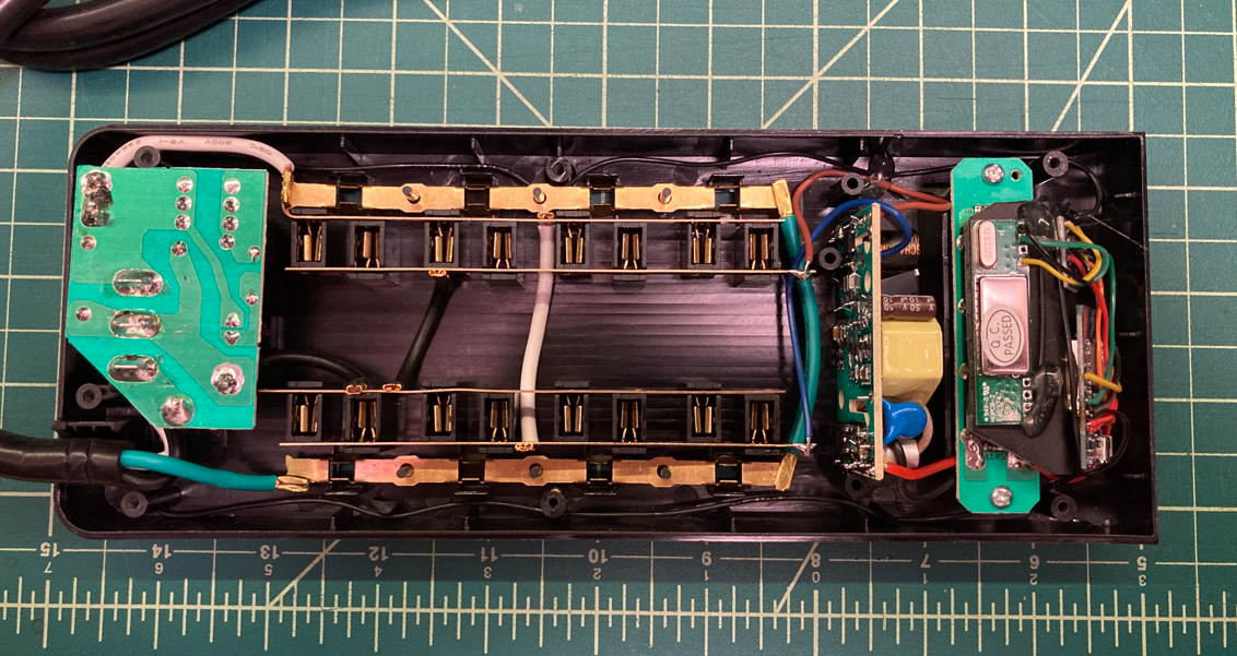
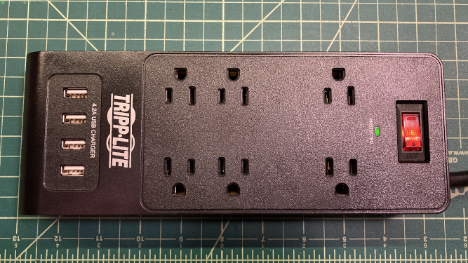
I finally settled on installing it in a Tripp Lite TLP664USBB surge protector that included USB ports, https://tripplite.eaton.com/6-outlet-surge-protector-with-4-usb-ports-6-foot-1800-joules-black~TLP664USBB. This allowed the Wemos to get its power directly from the 5 volt USB ports. The power strip is used for other purposes and none of it looks odd or attention getting. I had to loop the antenna around the inside of the power strip. This didn’t present any problems as I was careful to isolate the electronics by sealing it with silicon calk. The Wemos module was placed so that the mini USB port was still accessible, should any programming need to be done later.
This project will likely expand as time goes on, with the option to decode multiple sensors types from a single microcontroller. But for now, this will do what I need.