Modified Volantex Ranger 600 Controller
The stock Volantex Ranger 600 TX is as basic as any TX can get. The undocumented throw reversals prompted a closer look at the controller. The terms controller and TX apply to the hand held radio controller used to operate the remote controlled plane, TX will be used going forward.
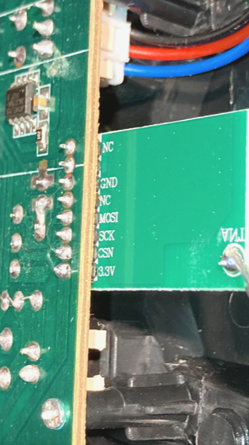
One item that was replaced with a yellow LED was the beep indicator. Since a lot of bench testing was going to take place, the blinking LED would be less annoying. The stock wireless antenna was replaced with a threaded mounting antenna. Photos of the inside of the TX were taken and it seems that it uses something similar to the nRF24L0 2.4Ghz transceiver. However the RF module was strictly for transmitting only, MOSI.
The stock antenna had a solder point on the RF module with no ground pin nearby. The stock antenna was a single core insulated wire that was a quarter wavelength measuring 3.1cm. The 2.4Ghz range has a full wavelength around 12.5cm , ie Speed of Light(m/s) / Frequency(cycles/s) = Wavelength(m/s). Do the math, 299,792,458 meters per second / 2,400,000,000 cycles per second = .1249 meters.
The RX responded to the TX predictably after fully testing how throw reversals and arming behaved. Some key take aways were the following items.
Throws could be reversed by holding either the elevator or rudder at full deflection in either direction and holding it there until an indication beep.
Gyro calibration is done by holding the left horn to the lower left then holding the right horn to the lower right until an indication beep.
Gyro calibration is based on the current throw setting, so set throws first then calibrate the gyros.
Arming the motor is done by raising the throttle horn up full then back down full, the TX will beep with each motion.
Once armed, if the RX battery is removed while the TX remains on, and the RX battery is re-connected, arming will remain on.
Only after removing the RX battery and power cycling the TX will the motor return to a disarmed state.
Now with the radio controls fully understood, it was time to return to field for some range tests with new TX setup. The location had to allow for a large area, in the event the plane drifted after loosing signal lock. One other flight parameter was for the flight to stay below 50 feet. Both of these were essential factors due to a countering factor that almost led to the plane being lost, glide ratio increase.
The failsafe typically is good option, especially when it can be defined or programmed. However the Ranger 600 has a factory defined failsafe of 50 percent throttle. This was undesirable because the flight was operated at less than 50 percent throttle. When the plane began to loose signal, the throttle increased causing the plane to have a larger glide ratio. The signal was lost around 700 meters out and it looped and drifted for another 250 meters. It was less than 50 meters away from entering an area that would make recovery difficult.
Knowing the exact radio range was not possible with the existing hardware. The ESP32-Cam module wasn’t designed to plot that information. The TX did not have a receive function, so knowing the RSSI value wasn’t available. In the next post, the nRF24L0 will used as a RSSI plotting tool.