RSSI Interference
Before diving right in on this topic, we should ask what is RSSI and why does interference matter. First off, RSSI stands for Received Signal Strength Indicator and it’s a measurement of the radio frequency power level present at the receiver (1 and 2). A radio frequency transmitter typically has a fixed power output level. As a receiver moves away or around the transmitter, the received power level varies. RSSI is a way to measure that variation. Typically the variation follows a steady change when the receiver and transmitter have an unblocked line of sight of each other. However, objects or materials in the air can cause interference, as well as other RF transmitters that are in range. Since RF signals are only detectable with equipment, an operator of RF equipment would be unaware of the signal strength in the absence of some type of RSSI. So RSSI is a valuable tool to know the operation of the RF equipment, its limits, and factors that might further influence it.
The ESP32-Cam project provides up to 3 possible RSSI values for 802.11 transmitters within its range of detection. The ESP32-Cam also provides a total number of detected 802.11 transmitters in range. For those 3 APs with the strongest signal strength, the ESP32-Cam provides the network name, RSSI value, and whether encryption is enabled. Here is an example, names have been changed to protect the innocent.
Networks	SSID-1	RSSID-1	Enc-1	SSID-2	RSSID-2	Enc-2	SSID-3	RSSID-3	Enc-3
5	MyWifiNet	-83	*	OrbNetwork	-85	*	OrbNetwork	-86	*
5	Pickers	-89	 	KwikPin	-91	*	Vinno	-93	*
10	JailBreak	-84	*	OrbNetwork	-84	*	MyWifiNet	-87	*
4	KwikPin	-89	*	HaloNet	-89	*	KwikPin	-91	*
7	HaloNet	-82	*	Pickers	-82	 	MixNMatch	-89	*
14	MyWifiNet	-85	*	OrbNetwork	-86	*	HaloNet	-86	*
2	Sluther	-92	*	MixNMatch	-95	*		0
10	MyWifiNet	-87	*	KwikPin	-87	*	HaloNet	-87	*
10	MyWifiNet	-87	*	OrbNetwork	-88	*	OrbNetwork	-89	*
From the example above, these networks had more than 1 AP in range of the ESP32-Cam, “KwikPin” and “OrbNetwork”. As the ESP32-Cam location changed, the networks and RSSI values also changed. This can be used to create a heat map. But the date has some limitations. Since any network that has more than 1 AP can be read, it fails to provide details about which unique AP it is reading. The third line in the example lists “OrbNetwork”. We have no way of knowing which AP this is from the first line readings. Another significant limitation of the ESP32-Cam is it only provides higher level 802.11 RSSI values. There are other devices that use that same radio frequency that it can not detect.
Another module that can be used to provide RSSI values from lower level RF devices is the NRF24L0. This module is capable of operating as a transceiver, which seems to be its primary use case. However the focus here will be using it to provide detected RSSI values. This code base was used for examples demonstrated below (3).
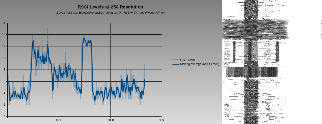
The image above are the same sample of RSSI readings, but presented in the time (left) and frequency (right) domains. The code used to take these readings is here.
#include <SPI.h>

// Increased define CHANNELS from 64 to 256 in attempt to increase resolution

// Poor Man's Wireless 2.4GHz Scanner
//
// uses an nRF24L01p connected to an Arduino
//
// Cables are:
//     SS       -> 10
//     MOSI     -> 11
//     MISO     -> 12
//     SCK      -> 13
//
// and CE       ->  9
//
// created March 2011 by Rolf Henkel
//

#define CE  9

unsigned long myTime;

// Array to hold Channel data (32 = 1 sec, 64 = 2 sec, 128 = 4 sec, 256 = 8 sec, etc)
#define CHANNELS  256
int channel[CHANNELS];

// greyscale mapping
int  line;
char grey[] = "0123456789";
// char grey[] = " .:-=+*aRW";

// nRF24L01P registers we need
#define _NRF24_CONFIG      0x00
#define _NRF24_EN_AA       0x01
#define _NRF24_RF_CH       0x05
#define _NRF24_RF_SETUP    0x06
#define _NRF24_RPD         0x09

// get the value of a nRF24L01p register
byte getRegister(byte r)
{
  byte c;

  PORTB &=~_BV(2);
  c = SPI.transfer(r&0x1F);
  c = SPI.transfer(0);
  PORTB |= _BV(2);

  return(c);
}

// set the value of a nRF24L01p register
void setRegister(byte r, byte v)
{
  PORTB &=~_BV(2);
  SPI.transfer((r&0x1F)|0x20);
  SPI.transfer(v);
  PORTB |= _BV(2);
}

// power up the nRF24L01p chip
void powerUp(void)
{
  setRegister(_NRF24_CONFIG,getRegister(_NRF24_CONFIG)|0x02);
  delayMicroseconds(130);
}

// switch nRF24L01p off
void powerDown(void)
{
  setRegister(_NRF24_CONFIG,getRegister(_NRF24_CONFIG)&~0x02);
}

// enable RX
void enable(void)
{
    PORTB |= _BV(1);
}

// disable RX
void disable(void)
{
    PORTB &=~_BV(1);
}

// setup RX-Mode of nRF24L01p
void setRX(void)
{
  setRegister(_NRF24_CONFIG,getRegister(_NRF24_CONFIG)|0x01);
  enable();
  // this is slightly shorter than
  // the recommended delay of 130 usec
  // - but it works for me and speeds things up a little...
  delayMicroseconds(100);
}

// scanning all channels in the 2.4GHz band
void scanChannels(void)
{
  disable();
  for( int j=0 ; j<200  ; j++)
  {
    for( int i=0 ; i<CHANNELS ; i++)
    {
      // select a new channel
      setRegister(_NRF24_RF_CH,(128*i)/CHANNELS);

      // switch on RX
      setRX();

      // wait enough for RX-things to settle
      delayMicroseconds(40);

      // this is actually the point where the RPD-flag
      // is set, when CE goes low
      disable();

      // read out RPD flag; set to 1 if
      // received power > -64dBm
      if( getRegister(_NRF24_RPD)>0 )   channel[i]++;
    }
  }
}

// outputs channel data as a simple grey map
void outputChannels(void)
{
  int norm = 0;

  // find the maximal count in channel array
  for( int i=0 ; i<CHANNELS ; i++)
    if( channel[i]>norm ) norm = channel[i];

  // now output the data
  for( int i=0 ; i<CHANNELS ; i++)
  {
    int pos;

    // calculate grey value position
    if( norm!=0 ) pos = (channel[i]*10)/norm;
    else          pos = 0;

    // boost low values
    if( pos==0 && channel[i]>0 ) pos++;

    // clamp large values
    if( pos>9 ) pos = 9;

    // print it out
    Serial.print(grey[pos]);
    Serial.print(',');
    channel[i] = 0;
  }

  // indicate overall power
  Serial.print(norm);
  Serial.print(',');
  myTime = millis();
  Serial.print(myTime);
  Serial.println(',');
}


void setup()
{
  Serial.begin(57600);

  // Setup SPI
  SPI.begin();
  // Clock Speed, Bit Order, and Data Mode
  SPI.beginTransaction(SPISettings(20000000, MSBFIRST, SPI_MODE0));

  // Activate Chip Enable
  pinMode(CE,OUTPUT);
  disable();

  // now start receiver
  powerUp();

  // switch off Shockburst
  setRegister(_NRF24_EN_AA,0x0);

  // make sure RF-section is set properly
  // - just write default value...
  setRegister(_NRF24_RF_SETUP,0x0F);

  // reset line counter
  line = 0;
}

void loop()
{
  // do the scan
  scanChannels();

  // output the result
  outputChannels();
}
The code generates text that is output on an Arduino Uno serial transmit pin. Putty was used to log the serial stream and save it as a csv file. The resulting file was opened as a spreadsheet and the last 2 columns were used to chart the time domain RSSI values. The frequency domain values could be visualized in the spreadsheet as well using cell value conditions, but this wasn’t efficient. Python was used instead, but the resulting image required some post process normalization, here is the code.
from numpy import genfromtxt
numpy_array = genfromtxt('C:/Share/Python/RSSI Readings_New_256-Resolution.csv', delimiter=',')

import cv2
cv2.imwrite('C:/Share/Python/RSSI Readings_New_256-Resolution.png', numpy_array)
Python libraries used in the example will need to be installed. These steps worked for the examples above. The last video was relevant for the Linux hosts.
There are commercial products that can provide visibility, but the costs for these devices put them out of reach for casual users. Here are list of resources for products used for professional work.
- https://www.oscium.com/spectrum-analyzers/wipry-2500x
- https://shop.metageek.com/products/metageek-complete
- https://shop.nutsaboutnets.com/
In addition to the cost, these devices aren’t designed to be placed on a remote controlled device or carried aloft using other means due to their size, weight, and power requirements. The RSSI value readings offered by the NRF24L0 provides a wealth of information for its low cost and small size. Be aware though that the manufacturer has indicated that this device should not be used for new designs (4 and 5). Nordic semiconductors is currently offering nRF9 and nRF5 series devices for new designs. Of these new device offerings, Adafruit offers a guide for the nRF51822 (6).
For operators of radio controlled equipment, RSSI readings are often a built in feature. FlySky offers a reasonably priced TX and their RX options offer RSSI values back to the TX. These readings provide the operator with information that can prevent a loss of signal condition. However, the RSSI values the RX provides is also limited in detail. It only provides its RSSI value from the bound TX. The operator has no way of knowing about other devices transmitting in the area. Although FlySky has limited RSSI data, it does offer other features from its iBus support, which will be covered in the next post.
Footnotes
(1) https://en.wikipedia.org/wiki/Received_signal_strength_indication
(2) https://randomnerdtutorials.com/nrf24l01-2-4ghz-rf-transceiver-module-with-arduino/
(3) https://forum.arduino.cc/t/poor-mans-2-4-ghz-scanner/54846
(4) https://www.nordicsemi.com/Products/nRF24-series
(5) https://www.nordicsemi.com/-/media/Publications/WQ-Product-guide/Wireless-Q—Q1—Product-Guide.pdf
(6) https://learn.adafruit.com/introducing-the-adafruit-bluefruit-le-sniffer?view=all