FlySky RSSI Telemetry
RSSI, which stands for received signal strength indication, was covered in the last post. The topic covered how the Nordic Seminconductor’s nRF240L0 wireless device could be used to measure RSSI values. Those values reveal the reliability of the radio controlled reception and interference that might be present. RSSI telemetry is basically a tool to see invisible radio waves that operate on the same operating frequency as the radio controller (TX) and receiver (RX).
FlySky is a manufacturer based out of China that has been in operation since 2006. They produce consumer electronics in the form of remote controlled radio transmitters and receivers for use in the operation of land, water, or air scaled models. Research and development takes place in Shenzhen, while Dongguan is where the products are manufactured. The electrical communications protocol used in the product line is called IBUS.
Oscar Liang has a blog that gives great details on RC protocols, which can be found here, https://oscarliang.com/rc-protocols. He mentions IBUS, which is a bidirectional serial protocol.
Another article in Wikipedia mentioned that ibus stands for intelligent input bus and was authored by Peng Huang. The iBus protocol it mentioned was initially released in August 2008, with its most recent release as of this writing on February 21, 2021. I’m not sure if the two are related, but thought it wise to include anyway.
In this post I’ll be covering the RSSI telemetry features of the FlySky FS-i6X TX and FS-iA6B RX. Here is a video with an introduction to the FS-i6X TX, published Oct 11th, 2016.
This next video covers how to bind the FS-iA6B RX with the TX, along with the setup of the FS-CVT01 external voltage sensor that utilizes the IBUS protocol, published May 3rd, 2020.
This next video demonstrates a field modification to accurately measure the RX battery voltage, which was published May 12, 2021.
Although the IBUS protocol was briefly mentioned, I will not cover it further in this post. Instead, the focus will return to RSSI telemetry feature of the FlySky FS-i6X TX and FS-iA6B RX. These are built in features that do not require any firmware or hardware modifications. I just wanted to briefly mention the IBUS sensors and hardware modifications, as well as the availability of third party firmware for them.
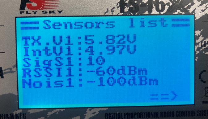
This video provides many of the operational procedures for operating the FlySky TX and how to get RSSI values on the display of the TX, published April 12th, 2018.
This should provide plenty of background to serve as an introduction and basic operation of the FlySky TX and RX RSSI telemetry.
The following is a GPS plot of RSSI values at -70dBM with the RX in a stationary location and the TX carried around it. The GPS readings were taken with the iphone app SensorLog and visual readings were read from the TX while walking around the RX. The GPS plot was made with Viking. The plot consists of two measurements, mainly due to work crews returning to the field to mow the grass.
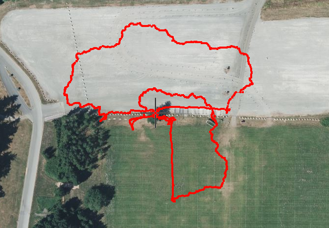
The location of the RX was moved from the field to the gravel parking lot, so the black cross hairs represents that new location.
The RSSI values would dip and rise around the -70dBM level as the attempt was made to maintain that ideal reading on the TX display. It was interesting to see the plot once the readings were made and how the sun might have been a factor.
[sphere 3859]
Another field test was done with a complete encircling of the RX this time. Observations of the TX reception influenced by positioning was noted. The TX appears to have the best reception when held with the TX back toward the RX, as demonstrated with this long range flight, dated Nov 18th, 2018.
The RF beam shares the same characteristics as a flashlight. As the TX was pointed toward the ground or rotated away from the RX, the RSSI values also dropped. The best reception always followed when the back of the TX was pointed at the RX. Based on this video, with the FS-i6X TX opened, the antenna is actually located inside the handle and not in what appears to be an antenna notch.
The typical distance between the TX and RX that maintained a -70dBM level was around 35 meters. The RX was sitting at ground level, where the TX was at 1.5 meters above the ground. Measurements with the nRF24L0 were also made of the area with no indications of external RF interference.
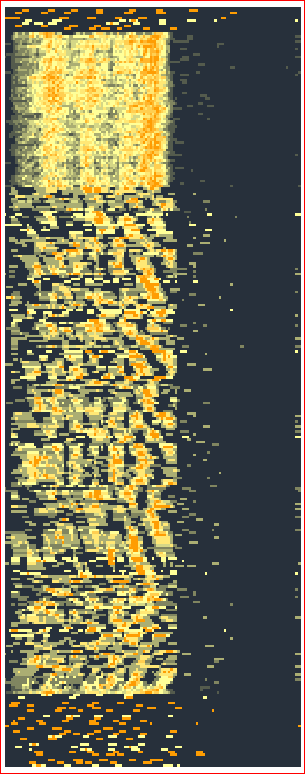
The plot shows the RX radio active at the top, followed by the powering on of the TX. This shows most of the RF plotted by the nRF24L0. Once the RX was placed and the TX moved away, does the plot thin out during the survey. At the bottom of the plot, the TX appears to be powered off with just the RX active. No other RF signals appear to be a factor, so the plot is fairly accurate.
The next post will cover the iBus protocol and how to add sensors to the TX readout with the intent of having a ground based data reading.