Visualizing Data with Processing
The purpose of this post is to demonstrate how to use Processing to present data in a visual way. The methods used in this post will be based on the work done by M.Furkan Bahat.
Source – https://mfurkanbahat.blogspot.com/2014/11/artificial-horizon-and-compass-using.html
The hardware used in this demonstration will be the following:
GY-521 MPU6050
Arduino Uno
ESP32-Cam
ESP32-USB-Module
Patch wiring
USB cables
Windows 10 laptop
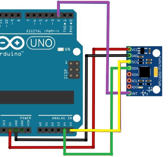
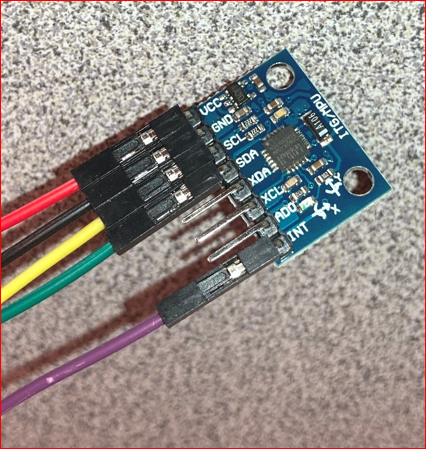
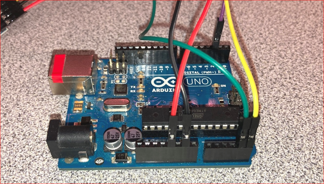
The MPU6050 is connected to the Arduino Uno using the following pin connections, as shown in the images below.
Red patch wire from VCC to 5V
Black patch wire from GND to GND
Yellow patch wire from SCL to A5
Green patch wire from SDA to A4
Purple patch wire from INT to Digital Pin 2
The Arduino code used is shown below, this was sourced from M.Furkan Bahat’s work. Although the libraries I2Cdev.h and MPU6050_6Axis_MotionApps20.h needed to be installed, sourced here https://github.com/jrowberg/i2cdevlib, no additional changes were needed.
// M.Furkan Bahat , November 2014
// For more information  http://mfurkanbahat.blogspot.com.tr/

// Source - https://mfurkanbahat.blogspot.com/2014/11/artificial-horizon-and-compass-using.html
// ArtificialHorizonCompass.ino

// Needed https://github.com/jrowberg/i2cdevlib for I2Cdev.h and MPU6050_6Axis_MotionApps20.h

#include "I2Cdev.h"
#include "MPU6050_6Axis_MotionApps20.h"

#if I2CDEV_IMPLEMENTATION == I2CDEV_ARDUINO_WIRE
    #include "Wire.h"
#endif

MPU6050 mpu;
#define OUTPUT_READABLE_YAWPITCHROLL
#define LED_PIN 13
bool blinkState = false;

// MPU control/status vars
bool dmpReady = false;  // set true if DMP init was successful
uint8_t mpuIntStatus;   // holds actual interrupt status byte from MPU
uint8_t devStatus;      // return status after each device operation (0 = success, !0 = error)
uint16_t packetSize;    // expected DMP packet size (default is 42 bytes)
uint16_t fifoCount;     // count of all bytes currently in FIFO
uint8_t fifoBuffer[64]; // FIFO storage buffer

// orientation/motion vars
Quaternion q;           // [w, x, y, z]         quaternion container
VectorInt16 aa;         // [x, y, z]            accel sensor measurements
VectorInt16 aaReal;     // [x, y, z]            gravity-free accel sensor measurements
VectorInt16 aaWorld;    // [x, y, z]            world-frame accel sensor measurements
VectorFloat gravity;    // [x, y, z]            gravity vector
float euler[3];         // [psi, theta, phi]    Euler angle container
float ypr[3];           // [yaw, pitch, roll]   yaw/pitch/roll container and gravity vector

// packet structure for InvenSense teapot demo
uint8_t teapotPacket[14] = { '$', 0x02, 0,0, 0,0, 0,0, 0,0, 0x00, 0x00, '\r', '\n' };

// ================================================================
// ===               INTERRUPT DETECTION ROUTINE                ===
// ================================================================

volatile bool mpuInterrupt = false;     // indicates whether MPU interrupt pin has gone high
void dmpDataReady() {
    mpuInterrupt = true;
}

// ================================================================
// ===                      INITIAL SETUP                       ===
// ================================================================

void setup() {
    // join I2C bus (I2Cdev library doesn't do this automatically)
    #if I2CDEV_IMPLEMENTATION == I2CDEV_ARDUINO_WIRE
        Wire.begin();
        TWBR = 24; // 400kHz I2C clock (200kHz if CPU is 8MHz)
    #elif I2CDEV_IMPLEMENTATION == I2CDEV_BUILTIN_FASTWIRE
        Fastwire::setup(400, true);
    #endif

    // initialize serial communication
    // (115200 chosen because it is required for Teapot Demo output, but it's
    // really up to you depending on your project)
    Serial.begin(115200);
    while (!Serial); // wait for Leonardo enumeration, others continue immediately
    mpu.initialize();
    devStatus = mpu.dmpInitialize();

    // supply your own gyro offsets here, scaled for min sensitivity
    mpu.setXGyroOffset(220);
    mpu.setYGyroOffset(76);
    mpu.setZGyroOffset(-85);
    mpu.setZAccelOffset(1788); // 1688 factory default for my test chip

    // make sure it worked (returns 0 if so)
    if (devStatus == 0) {
        mpu.setDMPEnabled(true);

        // enable Arduino interrupt detection
        //Serial.println(F("Enabling interrupt detection (Arduino external interrupt 0)..."));
        attachInterrupt(0, dmpDataReady, RISING);
        mpuIntStatus = mpu.getIntStatus();

        // set our DMP Ready flag so the main loop() function knows it's okay to use it
        //Serial.println(F("DMP ready! Waiting for first interrupt..."));
        dmpReady = true;

        // get expected DMP packet size for later comparison
        packetSize = mpu.dmpGetFIFOPacketSize();
    } else {

        Serial.print(devStatus);
        Serial.println(F(")"));
    }

    // configure LED for output
    pinMode(LED_PIN, OUTPUT);
}

// ================================================================
// ===                    MAIN PROGRAM LOOP                     ===
// ================================================================

void loop() {
    // if programming failed, don't try to do anything
    if (!dmpReady) return;

    // wait for MPU interrupt or extra packet(s) available
    while (!mpuInterrupt && fifoCount < packetSize) {

    }

    // reset interrupt flag and get INT_STATUS byte
    mpuInterrupt = false;
    mpuIntStatus = mpu.getIntStatus();

    // get current FIFO count
    fifoCount = mpu.getFIFOCount();

    // check for overflow (this should never happen unless our code is too inefficient)
    if ((mpuIntStatus & 0x10) || fifoCount == 1024) {
        // reset so we can continue cleanly
        mpu.resetFIFO();
        //Serial.println(F("FIFO overflow!"));

    // otherwise, check for DMP data ready interrupt (this should happen frequently)
    } else if (mpuIntStatus & 0x02) {
        // wait for correct available data length, should be a VERY short wait
        while (fifoCount < packetSize) fifoCount = mpu.getFIFOCount();

        // read a packet from FIFO
        mpu.getFIFOBytes(fifoBuffer, packetSize);

        // track FIFO count here in case there is > 1 packet available
        // (this lets us immediately read more without waiting for an interrupt)
        fifoCount -= packetSize;

        #ifdef OUTPUT_READABLE_QUATERNION
            // display quaternion values in easy matrix form: w x y z
            mpu.dmpGetQuaternion(&q, fifoBuffer);
            Serial.print("quat\t");
            Serial.print(q.w);
            Serial.print("\t");
            Serial.print(q.x);
            Serial.print("\t");
            Serial.print(q.y);
            Serial.print("\t");
            Serial.println(q.z);
        #endif

        #ifdef OUTPUT_READABLE_EULER
            // display Euler angles in degrees
            mpu.dmpGetQuaternion(&q, fifoBuffer);
            mpu.dmpGetEuler(euler, &q);
            Serial.print("euler\t");
            Serial.print(euler[0] * 180/M_PI);
            Serial.print("\t");
            Serial.print(euler[1] * 180/M_PI);
            Serial.print("\t");
            Serial.println(euler[2] * 180/M_PI);
        #endif

        #ifdef OUTPUT_READABLE_YAWPITCHROLL
            // display Euler angles in degrees
            mpu.dmpGetQuaternion(&q, fifoBuffer);
            mpu.dmpGetGravity(&gravity, &q);
            mpu.dmpGetYawPitchRoll(ypr, &q, &gravity);
            //Serial.print("Phi: ");
            Serial.print(ypr[2] * 18/M_PI);
            //Serial.print("\t theta: ");
            Serial.print(" ");
            Serial.print(ypr[1] * 180/M_PI);
            //Serial.print("\t Psi: ");
            Serial.print(" ");
            Serial.println(ypr[0] * 180/M_PI);
            //delay(100);
        #endif

        #ifdef OUTPUT_READABLE_REALACCEL
            // display real acceleration, adjusted to remove gravity
            mpu.dmpGetQuaternion(&q, fifoBuffer);
            mpu.dmpGetAccel(&aa, fifoBuffer);
            mpu.dmpGetGravity(&gravity, &q);
            mpu.dmpGetLinearAccel(&aaReal, &aa, &gravity);
            Serial.print("areal\t");
            Serial.print(aaReal.x);
            Serial.print("\t");
            Serial.print(aaReal.y);
            Serial.print("\t");
            Serial.println(aaReal.z);
        #endif

        #ifdef OUTPUT_READABLE_WORLDACCEL
            // display initial world-frame acceleration, adjusted to remove gravity
            // and rotated based on known orientation from quaternion
            mpu.dmpGetQuaternion(&q, fifoBuffer);
            mpu.dmpGetAccel(&aa, fifoBuffer);
            mpu.dmpGetGravity(&gravity, &q);
            mpu.dmpGetLinearAccel(&aaReal, &aa, &gravity);
            mpu.dmpGetLinearAccelInWorld(&aaWorld, &aaReal, &q);
            Serial.print("aworld\t");
            Serial.print(aaWorld.x);
            Serial.print("\t");
            Serial.print(aaWorld.y);
            Serial.print("\t");
            Serial.println(aaWorld.z);
        #endif

        #ifdef OUTPUT_TEAPOT
            // display quaternion values in InvenSense Teapot demo format:
            teapotPacket[2] = fifoBuffer[0];
            teapotPacket[3] = fifoBuffer[1];
            teapotPacket[4] = fifoBuffer[4];
            teapotPacket[5] = fifoBuffer[5];
            teapotPacket[6] = fifoBuffer[8];
            teapotPacket[7] = fifoBuffer[9];
            teapotPacket[8] = fifoBuffer[12];
            teapotPacket[9] = fifoBuffer[13];
            Serial.write(teapotPacket, 14);
            teapotPacket[11]++; // packetCount, loops at 0xFF on purpose
        #endif

        // blink LED to indicate activity
        blinkState = !blinkState;
        digitalWrite(LED_PIN, blinkState);
    }
}
The Processing 3 Code used is shown below. Again, this was sourced from M.Furkan Bahat’s work. The cc.arduino was not installed by default and was required. In addition, these changes were made to the code due to issues with the version of Processing used, which was version 3.5.4.
// size(W, H); Processing didn't like this
size(1400, 700);
//Thanks to Adrian Fernandez
//Communication updates by M.Furkan Bahat November 2014
//For more information http://mfurkanbahat.blogspot.com.tr/
// Source - https://mfurkanbahat.blogspot.com/2014/11/artificial-horizon-and-compass-using.html
// ArtificialHorizonCompass.pde
// Works with Arduino Uno and live data
// Not working with stored data from ESP23-Cam MicroSD log file
// See - https://learn.sparkfun.com/tutorials/connecting-arduino-to-processing/all
import processing.serial.*;
import cc.arduino.*;
int W=1400; //My Laptop's screen width
int H=700; //My Laptop's screen height
float Pitch;
float Bank;
float Azimuth;
float ArtificialHoizonMagnificationFactor=0.7;
float CompassMagnificationFactor=0.85;
float SpanAngle=120;
int NumberOfScaleMajorDivisions;
int NumberOfScaleMinorDivisions;
PVector v1, v2;
Serial port;
float Phi; //Dimensional axis
float Theta;
float Psi;
void setup()
{
// size(W, H); WRONG - Processing didn't like this
size(1400, 700);
rectMode(CENTER);
smooth();
strokeCap(SQUARE);//Optional
println(Serial.list()); //Shows your connected serial ports
port = new Serial(this, Serial.list()[0], 115200);
//Up there you should select port which arduino connected and same baud rate.
port.bufferUntil('\n');
}
void draw()
{
background(0);
translate(W/4, H/2.1);
MakeAnglesDependentOnMPU6050();
Horizon();
rotate(-Bank);
PitchScale();
Axis();
rotate(Bank);
Borders();
Plane();
ShowAngles();
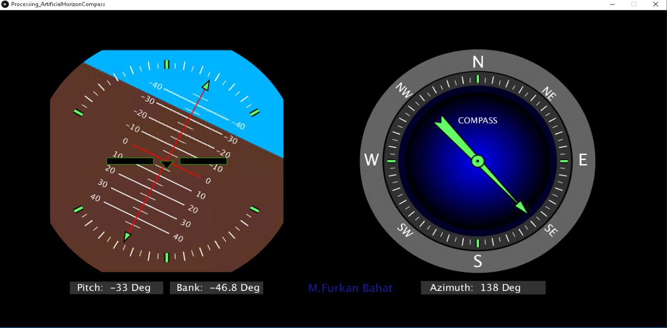
Compass();
ShowAzimuth();
}
void serialEvent(Serial port) //Reading the datas by Processing.
{
String input = port.readStringUntil('\n');
if(input != null){
input = trim(input);
String[] values = split(input, " ");
if(values.length == 3){
float phi = float(values[0]);
float theta = float(values[1]);
float psi = float(values[2]);
print(phi);
print(theta);
println(psi);
Phi = phi;
Theta = theta;
Psi = psi;
}
}
}
void MakeAnglesDependentOnMPU6050()
{
Bank =-Phi/5;
Pitch=Theta*10;
Azimuth=Psi;
}
void Horizon()
{
scale(ArtificialHoizonMagnificationFactor);
noStroke();
fill(0, 180, 255);
rect(0, -100, 900, 1000);
fill(95, 55, 40);
rotate(-Bank);
rect(0, 400+Pitch, 900, 800);
rotate(Bank);
rotate(-PI-PI/6);
SpanAngle=120;
NumberOfScaleMajorDivisions=12;
NumberOfScaleMinorDivisions=24;
CircularScale();
rotate(PI+PI/6);
rotate(-PI/6);
CircularScale();
rotate(PI/6);
}
void ShowAzimuth()
{
fill(50);
noStroke();
rect(20, 470, 440, 50);
int Azimuth1=round(Azimuth);
textAlign(CORNER);
textSize(35);
fill(255);
text("Azimuth: "+Azimuth1+" Deg", 80, 477, 500, 60);
textSize(40);
fill(25,25,150);
text("M.Furkan Bahat", -350, 477, 500, 60);
}
void Compass()
{
translate(2*W/3, 0);
scale(CompassMagnificationFactor);
noFill();
stroke(100);
strokeWeight(80);
ellipse(0, 0, 750, 750);
strokeWeight(50);
stroke(50);
fill(0, 0, 40);
ellipse(0, 0, 610, 610);
for (int k=255;k>0;k=k-5)
{
noStroke();
fill(0, 0, 255-k);
ellipse(0, 0, 2*k, 2*k);
}
strokeWeight(20);
NumberOfScaleMajorDivisions=18;
NumberOfScaleMinorDivisions=36;
SpanAngle=180;
CircularScale();
rotate(PI);
SpanAngle=180;
CircularScale();
rotate(-PI);
fill(255);
textSize(60);
textAlign(CENTER);
text("W", -375, 0, 100, 80);
text("E", 370, 0, 100, 80);
text("N", 0, -365, 100, 80);
text("S", 0, 375, 100, 80);
textSize(30);
text("COMPASS", 0, -130, 500, 80);
rotate(PI/4);
textSize(40);
text("NW", -370, 0, 100, 50);
text("SE", 365, 0, 100, 50);
text("NE", 0, -355, 100, 50);
text("SW", 0, 365, 100, 50);
rotate(-PI/4);
CompassPointer();
}
void CompassPointer()
{
rotate(PI+radians(Azimuth));
stroke(0);
strokeWeight(4);
fill(100, 255, 100);
triangle(-20, -210, 20, -210, 0, 270);
triangle(-15, 210, 15, 210, 0, 270);
ellipse(0, 0, 45, 45);
fill(0, 0, 50);
noStroke();
ellipse(0, 0, 10, 10);
triangle(-20, -213, 20, -213, 0, -190);
triangle(-15, -215, 15, -215, 0, -200);
rotate(-PI-radians(Azimuth));
}
void Plane()
{
fill(0);
strokeWeight(1);
stroke(0, 255, 0);
triangle(-20, 0, 20, 0, 0, 25);
rect(110, 0, 140, 20);
rect(-110, 0, 140, 20);
}
void CircularScale()
{
float GaugeWidth=800;
textSize(GaugeWidth/30);
float StrokeWidth=1;
float an;
float DivxPhasorCloser;
float DivxPhasorDistal;
float DivyPhasorCloser;
float DivyPhasorDistal;
strokeWeight(2*StrokeWidth);
stroke(255);
float DivCloserPhasorLenght=GaugeWidth/2-GaugeWidth/9-StrokeWidth;
float DivDistalPhasorLenght=GaugeWidth/2-GaugeWidth/7.5-StrokeWidth;
for (int Division=0;Division<NumberOfScaleMinorDivisions+1;Division++)
{
an=SpanAngle/2+Division*SpanAngle/NumberOfScaleMinorDivisions;
DivxPhasorCloser=DivCloserPhasorLenght*cos(radians(an));
DivxPhasorDistal=DivDistalPhasorLenght*cos(radians(an));
DivyPhasorCloser=DivCloserPhasorLenght*sin(radians(an));
DivyPhasorDistal=DivDistalPhasorLenght*sin(radians(an));
line(DivxPhasorCloser, DivyPhasorCloser, DivxPhasorDistal, DivyPhasorDistal);
}
DivCloserPhasorLenght=GaugeWidth/2-GaugeWidth/10-StrokeWidth;
DivDistalPhasorLenght=GaugeWidth/2-GaugeWidth/7.4-StrokeWidth;
for (int Division=0;Division<NumberOfScaleMajorDivisions+1;Division++)
{
an=SpanAngle/2+Division*SpanAngle/NumberOfScaleMajorDivisions;
DivxPhasorCloser=DivCloserPhasorLenght*cos(radians(an));
DivxPhasorDistal=DivDistalPhasorLenght*cos(radians(an));
DivyPhasorCloser=DivCloserPhasorLenght*sin(radians(an));
DivyPhasorDistal=DivDistalPhasorLenght*sin(radians(an));
if (Division==NumberOfScaleMajorDivisions/2|Division==0|Division==NumberOfScaleMajorDivisions)
{
strokeWeight(15);
stroke(0);
line(DivxPhasorCloser, DivyPhasorCloser, DivxPhasorDistal, DivyPhasorDistal);
strokeWeight(8);
stroke(100, 255, 100);
line(DivxPhasorCloser, DivyPhasorCloser, DivxPhasorDistal, DivyPhasorDistal);
}
else
{
strokeWeight(3);
stroke(255);
line(DivxPhasorCloser, DivyPhasorCloser, DivxPhasorDistal, DivyPhasorDistal);
}
}
}
void Axis()
{
stroke(255, 0, 0);
strokeWeight(3);
line(-115, 0, 115, 0);
line(0, 280, 0, -280);
fill(100, 255, 100);
stroke(0);
triangle(0, -285, -10, -255, 10, -255);
triangle(0, 285, -10, 255, 10, 255);
}
void ShowAngles()
{
textSize(30);
fill(50);
noStroke();
rect(-150, 400, 280, 40);
rect(150, 400, 280, 40);
fill(255);
Pitch=Pitch/5;
int Pitch1=round(Pitch);
text("Pitch: "+Pitch1+" Deg", -20, 411, 500, 60);
text("Bank: "+Bank*100+" Deg", 280, 411, 500, 60);
}
void Borders()
{
noFill();
stroke(0);
strokeWeight(400);
rect(0, 0, 1100, 1100);
strokeWeight(200);
ellipse(0, 0, 1000, 1000);
fill(0);
noStroke();
rect(4*W/5, 0, W, 2*H);
rect(-4*W/5, 0, W, 2*H);
}
void PitchScale()
{
stroke(255);
fill(255);
strokeWeight(3);
textSize(24);
textAlign(CENTER);
for (int i=-4;i<5;i++)
{
if ((i==0)==false)
{
line(110, 50*i, -110, 50*i);
}
text(""+i*10, 140, 50*i, 100, 30);
text(""+i*10, -140, 50*i, 100, 30);
}
textAlign(CORNER);
strokeWeight(2);
for (int i=-9;i<10;i++)
{
if ((i==0)==false)
{
line(25, 25*i, -25, 25*i);
}
}
}
In this configuration, a view live of data with Processing was possible.
The next step was to capture a GY-521 data stream to a file. This data stream sample would be used for offline viewing. Putty was used to capture a log of the serial stream. The log file was edited so it only contained valid data, below is a sample.
0.02 -0.15 0.06
0.02 -0.22 0.11
0.01 -0.30 0.14
0.00 -0.38 0.17
-0.01 -0.45 0.21
-0.01 -0.52 0.24
-0.02 -0.59 0.28
-0.03 -0.66 0.31
-0.03 -0.73 0.35
-0.04 -0.80 0.38
-0.05 -0.87 0.42
-0.05 -0.94 0.45
-0.06 -1.00 0.49
-0.07 -1.07 0.53
-0.07 -1.13 0.56
-0.08 -1.19 0.59
-0.08 -1.25 0.63
-0.09 -1.32 0.66
-0.10 -1.38 0.70
-0.10 -1.44 0.74
-0.11 -1.50 0.77
-0.11 -1.56 0.80
-0.12 -1.61 0.84
The ESP32-Cam module will be used to stream log file back to Processing through its serial output. The ESP32-Cam module features an onboard MicroSD storage slot, with the memory card containing the log data in a file. Code was sourced that would serial output the log file line by line with delays between, the purpose being a mock-up of the GY-521 serial data stream generated by the Arduino Uno. Below is the code used.
Source – https://arduino.stackexchange.com/questions/63468/reading-text-line-by-line-from-sd
// MicroSD_Line-Read_Ver2.ino

// Source - https://arduino.stackexchange.com/questions/63468/reading-text-line-by-line-from-sd

#include "FS.h"
#include "SD_MMC.h"

void setup() {

  Serial.begin(115200);
  Serial.println("SDcard Testing....");

   if(!SD_MMC.begin()){
        Serial.println("Card Mount Failed");
        return;
    }
    uint8_t cardType = SD_MMC.cardType();

    if(cardType == CARD_NONE){
        Serial.println("No SD_MMC card attached");
        return;
    }

}


void loop() {

  readFile(SD_MMC, "/Log.txt");


  // put your main code here, to run repeatedly:
}


//Read a file in SD card
void readFile(fs::FS &fs, const char * path){

    File LogFile = fs.open(path);

    if(!LogFile){
        Serial.println("Failed to open file for reading");
        return;
    }

    while(LogFile.available()){
        String line = LogFile.readStringUntil('\n');
        Serial.println(line);
        delay(30);  // Mimics the live stream interval from the GY-521 sensor
    }
}
Reading the data from the MicroSD card was successful. The ESP32-Cam flash LED blinked when data was read. A delay was used to mimic the live stream interval from the GY-521 sensor, however this later proved to be inaccurate and at best an approximated guess. Below is that change made to the code.
delay(30); // Mimics the live stream interval from the GY-521 sensor
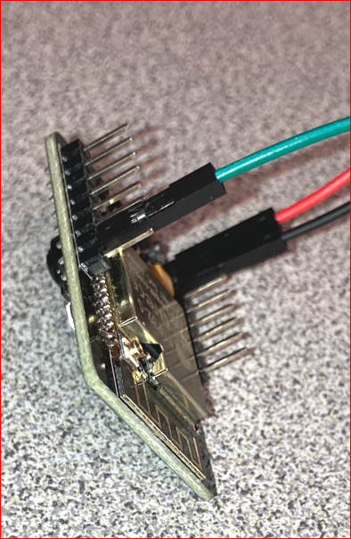
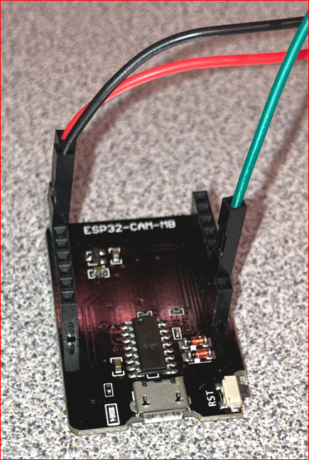
The serial data stream to console worked, but Processing did not show any stream data. The ESP32-Cam flash LED did not light, indicating no read functions. There is mention online about interrupts causing issues like this and referenced the following link, source – https://playground.arduino.cc/Main/DisablingAutoResetOnSerialConnection/. The issue was caused by an interrupt on the ESP32-Cam USB module board. This was corrected by isolating the connections from the ESP32-Cam to the USB module board. Only the following connections were used. Below are images of that configuration.
Black – GND
Red – 5V
Green – UTX
Processing then handled the data stream from the ESP32-Cam module the same as it did from the GY-521. There was some other trouble with Processing on system with multiple COM ports. The workaround was to disable those unused COM ports in order for the stream to work. This is something to be aware of with multiple simultaneous Arduino Uno or ESP32-USB-Module connections
These are some additional observations from the demonstration and expansion. Processing offers much more extensive visualization than the Arduino built in serial plotter. There is value in having playback options for stored data. The data stream playback rate doesn’t match the original source rate and proved to require a complex remedy. There is also noticeable drift of data values, an example of this is when the bearing does not return to its initial position, even though the sensor has.
Here is a demonstration of using filters for the MPU-6050 to correct value drift.
This is a link to the data-sheet of the MPU-6050
https://invensense.tdk.com/wp-content/uploads/2015/02/MPU-6000-Datasheet1.pdf
Here is a deeper dive into MPU-6050 programming with the Arduino
In an earlier post, https://www.cloudacm.com/?p=3655, it was mentioned that software provided as a service has a tendency to cease without warning. Dashware was listed in that group. Although the Dashware software is still available for download as of this writing, http://www.dashware.net/dashware-download/, it has been acquired by GoPro and has an extensive terms of use agreement. Fundamentally, the engine that provides the data visualization is FFMPEG, which is largely hidden by the end user interface’s black box. There are tutorial videos on how to operate the software available here, http://www.dashware.net/tutorial-videos/. GoPro has acquired other visualization providers, with the addition of ReelSteady to their portfolio. ReelSteady developed video stabilization technology, something that FFMPEG can perform as well. The trend of GoPro appears to be one of reinventing itself away from being just an action camera. Some may argue it’s too little or too late. Unlike the fate that visited Contour years before, https://www.geekwire.com/2013/contour-cofounder-we-showing-world-do/, GoPro now competes with a pervasive vast sea of image sensors in mobile devices. Unfortunately, if GoPro were to fail, that failure also encompasses the technology it has acquired.