ESP32-Cam NRF24L01 Radio Spectrum Data Logger
This post will cover recent uses of the NRF24L01 with the EPS32-Cam module. An earlier example used an the NRF24L01 module attached to an Arduino Uno, a laptop, and a logged putty session, details can be found here, https://www.cloudacm.com/?p=3836. This configuration had limitations due to its size, the required pieces of equipment, and operating steps. The purpose of this scanner type is to survey 2.4Ghz radio transmissions. The NRF module can detect power levels across the band and store those values into its register. The band resolution can increased, but doing so will increase the amount of time needed for the module to complete a scan. A microcontroller is used to operate the NRF module and to read the values stored in the module’s register. These readings can then be stored, in this case to microSD storage in the form of a CSV file. Below is an example of a plot.
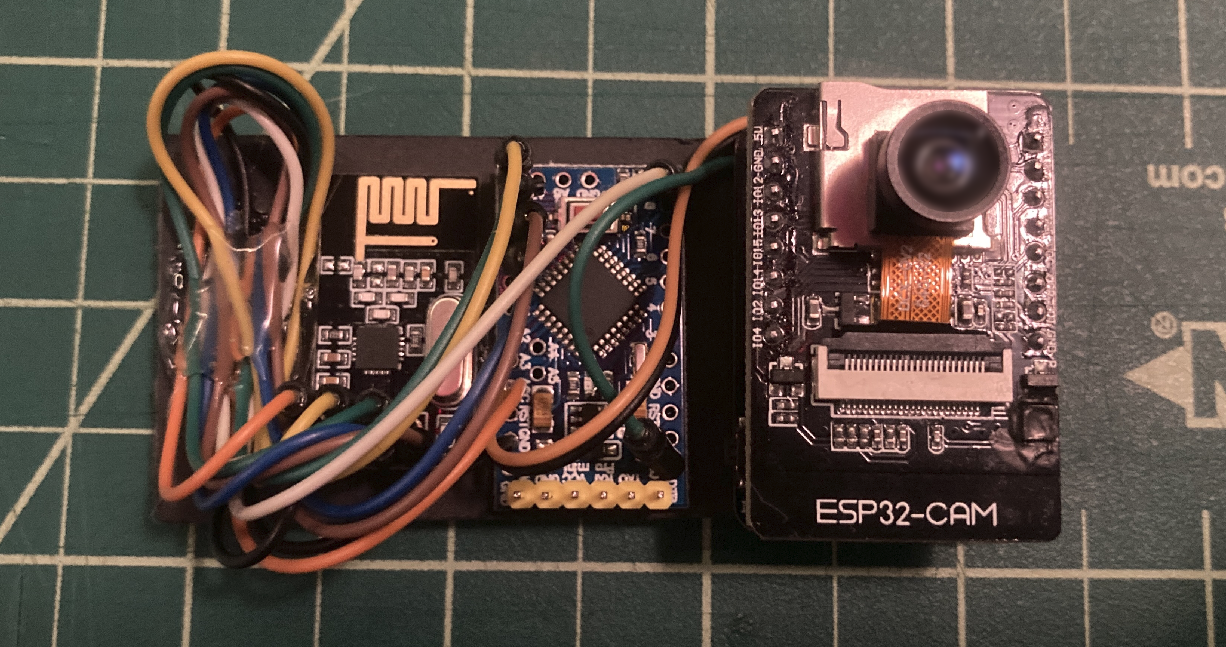
The second generation used an Arduino pro mini and the ESP32-Cam module. This design was smaller and mobile. Data logging was automatic and continuous. Using this device revealed an unknown source of RF which was from the console of the vehicle, shown in the video above.
After further investigation the source of the RF was the vehicle attempting to bind with a paired Bluetooth device. After removing the pairing, the vehicle no longer broadcasted RF.

Here is the python code used to plot the readings shown above.
# Python Code
import sys,os
import plotly.express as px


from numpy import genfromtxt
numpy_array = genfromtxt('NRF_Readings.csv', delimiter=',')

fig = px.imshow(numpy_array, color_continuous_scale='thermal')

fig.update_layout(width=640, height=1400, margin=dict(l=0, r=0, b=0, t=0), coloraxis_showscale=False)
fig.update_xaxes(showticklabels=False).update_yaxes(showticklabels=False)
# fig.show()

fig.write_image("NRF_Readings.png")


# Command - python3 NRF_Readings.py
# Source - https://plotly.com/python/heatmaps/

# https://plotly.com/python/imshow/
# https://pypi.org/project/plotly-express/
# https://www.cloudacm.com/?p=2674
# https://plotly.com/python/plotly-express/

# https://plotly.com/python/builtin-colorscales/

# aggrnyl     agsunset    blackbody   bluered     blues       blugrn      bluyl       brwnyl
# bugn        bupu        burg        burgyl      cividis     darkmint    electric    emrld
# gnbu        greens      greys       hot         inferno     jet         magenta     magma
# mint        orrd        oranges     oryel       peach       pinkyl      plasma      plotly3
# pubu        pubugn      purd        purp        purples     purpor      rainbow     rdbu
# rdpu        redor       reds        sunset      sunsetdark  teal        tealgrn     turbo
# viridis     ylgn        ylgnbu      ylorbr      ylorrd      algae       amp         deep
# dense       gray        haline      ice         matter      solar       speed       tempo
# thermal     turbid      armyrose    brbg        earth       fall        geyser      prgn
# piyg        picnic      portland    puor        rdgy        rdylbu      rdylgn      spectral
# tealrose    temps       tropic      balance     curl        delta       oxy         edge
# hsv         icefire     phase       twilight    mrybm       mygbm


# https://video.stackexchange.com/questions/32419/ffmpeg-vertical-pan-over-an-image-top-to-bottom-scrolling-effect

# Then make a video the scrolls the image.

# ffmpeg -f lavfi -i color=s=640x360 -i NRF24L01_Readings-128bit_MorningCommute_Aug14-0900_NoTimeStamp_NoTotalRF.png -filter_complex "[0][1]overlay=x=0:y=H-0.5*n" -vframes 6625 NRF24L01_Readings-128bit_MorningCommute_Aug14-0900_NoTimeStamp_NoTotalRF.mp4
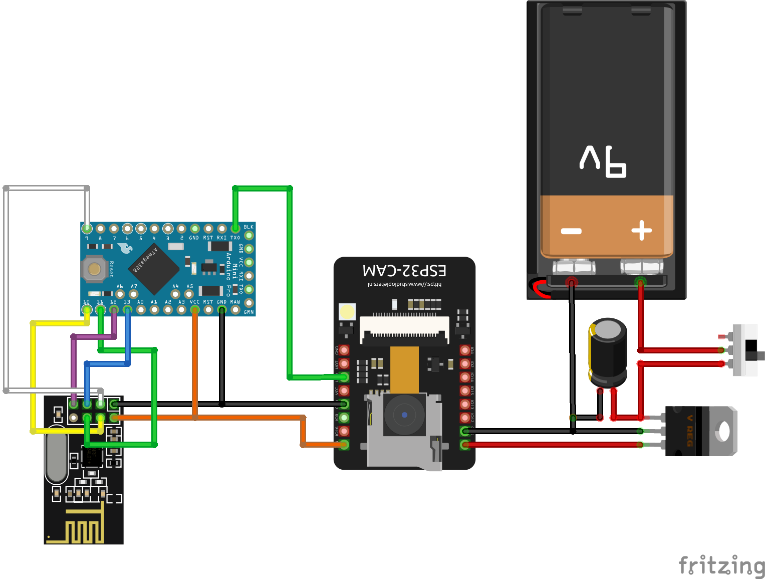
Here is the build interconnects and wiring when using the device with an external battery, however the build above used the ESP32-Cam module USB board.
Here is the microcontroller code used for the Arduino Pro Mini.
#include <SPI.h>

// Based off of this work, https://www.riyas.org/2013/12/working-quick-start-guide-for-nrf24l01.html

// Increased define CHANNELS from 64 to 256 in attempt to increase resolution

// Poor Man's Wireless 2.4GHz Scanner
//
// uses an nRF24L01p connected to an Arduino
//
// Cables are:
//     SS       -> 10   Chip Select Not - This is held to VCC to turn on chip, GPIO is not needed
//     MOSI     -> 11   Master Out Slave In - Now called PICO
//     MISO     -> 12   Master In Slave Out - Now called POCI
//     SCK      -> 13   Clock Signal
//
//     GND and VCC sould have a 10uf capacitor between them
//
// and CE       ->  9   Chip Enable - This is needed because SPI requires 2 way comms
//
// created March 2011 by Rolf Henkel
//

#define CE  9  // Chip Enable - This is needed because SPI requires 2 way comms

unsigned long myTime;

// Array to hold Channel data (32 = 1 sec, 64 = 2 sec, 128 = 4 sec, 256 = 8 sec, etc)
#define CHANNELS  64
int channel[CHANNELS];

// greyscale mapping
int  line;
char grey[] = "0123456789";
// char grey[] = " .:-=+*aRW";

// nRF24L01P registers we need
#define _NRF24_CONFIG      0x00
#define _NRF24_EN_AA       0x01
#define _NRF24_RF_CH       0x05
#define _NRF24_RF_SETUP    0x06
#define _NRF24_RPD         0x09

// get the value of a nRF24L01p register
byte getRegister(byte r)
{
  byte c;

  PORTB &=~_BV(2);
  c = SPI.transfer(r&0x1F);
  c = SPI.transfer(0);
  PORTB |= _BV(2);

  return(c);
}

// set the value of a nRF24L01p register
void setRegister(byte r, byte v)
{
  PORTB &=~_BV(2);
  SPI.transfer((r&0x1F)|0x20);
  SPI.transfer(v);
  PORTB |= _BV(2);
}

// power up the nRF24L01p chip
void powerUp(void)
{
  setRegister(_NRF24_CONFIG,getRegister(_NRF24_CONFIG)|0x02);
  delayMicroseconds(130);
}

// switch nRF24L01p off
void powerDown(void)
{
  setRegister(_NRF24_CONFIG,getRegister(_NRF24_CONFIG)&~0x02);
}

// enable RX
void enable(void)
{
    PORTB |= _BV(1);
}

// disable RX
void disable(void)
{
    PORTB &=~_BV(1);
}

// setup RX-Mode of nRF24L01p
void setRX(void)
{
  setRegister(_NRF24_CONFIG,getRegister(_NRF24_CONFIG)|0x01);
  enable();
  // this is slightly shorter than
  // the recommended delay of 130 usec
  // - but it works for me and speeds things up a little...
  delayMicroseconds(100);
}

// scanning all channels in the 2.4GHz band
void scanChannels(void)
{
  disable();
  for( int j=0 ; j<200  ; j++)
  {
    for( int i=0 ; i<CHANNELS ; i++)
    {
      // select a new channel
      setRegister(_NRF24_RF_CH,(64*i)/CHANNELS);

      // switch on RX
      setRX();

      // wait enough for RX-things to settle
      delayMicroseconds(40);

      // this is actually the point where the RPD-flag
      // is set, when CE goes low
      disable();

      // read out RPD flag; set to 1 if
      // received power > -64dBm
      if( getRegister(_NRF24_RPD)>0 )   channel[i]++;
    }
  }
}

// outputs channel data as a simple grey map
void outputChannels(void)
{
  int norm = 0;

  // find the maximal count in channel array
  for( int i=0 ; i<CHANNELS ; i++)
    if( channel[i]>norm ) norm = channel[i];

  // now output the data
  for( int i=0 ; i<CHANNELS ; i++)
  {
    int pos;

    // calculate grey value position
    if( norm!=0 ) pos = (channel[i]*10)/norm;
    else          pos = 0;

    // boost low values
    if( pos==0 && channel[i]>0 ) pos++;

    // clamp large values
    if( pos>9 ) pos = 9;

    // print it out
    Serial.print(grey[pos]);
    Serial.print(',');
    channel[i] = 0;
  }

  // indicate overall power
  Serial.print(norm);
  Serial.print(',');
  myTime = millis();
  Serial.print(myTime);
  Serial.println(',');
}


void setup()
{
  Serial.begin(57600);

  // Setup SPI
  SPI.begin();
  // Clock Speed, Bit Order, and Data Mode
  SPI.beginTransaction(SPISettings(20000000, MSBFIRST, SPI_MODE0));

  // Activate Chip Enable
  pinMode(CE,OUTPUT);
  disable();

  // now start receiver
  powerUp();

  // switch off Shockburst
  setRegister(_NRF24_EN_AA,0x0);

  // make sure RF-section is set properly
  // - just write default value...
  setRegister(_NRF24_RF_SETUP,0x0F);

  // reset line counter
  line = 0;
}

void loop()
{
  // do the scan
  scanChannels();

  // output the result
  outputChannels();
}
Here is the microcontroller code used for the ESP32-Cam module.
/*********
  Rui Santos
  Complete project details at https://RandomNerdTutorials.com/esp32-cam-take-photo-save-microsd-card

  IMPORTANT!!!
   - Select Board "AI Thinker ESP32-CAM"
   - GPIO 0 must be connected to GND to upload a sketch
   - After connecting GPIO 0 to GND, press the ESP32-CAM on-board RESET button to put your board in flashing mode

  Permission is hereby granted, free of charge, to any person obtaining a copy
  of this software and associated documentation files.
  The above copyright notice and this permission notice shall be included in all
  copies or substantial portions of the Software.

*********/

#include "esp_camera.h"
#include "FS.h"                // SD Card ESP32
#include "SD_MMC.h"            // SD Card ESP32
const char* NRFReadings = "/NRF24L01_Readings.csv";


// Pin definition for CAMERA_MODEL_AI_THINKER
#define PWDN_GPIO_NUM     32
#define RESET_GPIO_NUM    -1
#define XCLK_GPIO_NUM      0
#define SIOD_GPIO_NUM     26
#define SIOC_GPIO_NUM     27
#define Y9_GPIO_NUM       35
#define Y8_GPIO_NUM       34
#define Y7_GPIO_NUM       39
#define Y6_GPIO_NUM       36
#define Y5_GPIO_NUM       21
#define Y4_GPIO_NUM       19
#define Y3_GPIO_NUM       18
#define Y2_GPIO_NUM        5
#define VSYNC_GPIO_NUM    25
#define HREF_GPIO_NUM     23
#define PCLK_GPIO_NUM     22

unsigned long pictureNumber = 0;
unsigned long photodelay = 0; // Time counter for timed photos
unsigned long delaytime = 3000; // Time of delay between each photo


void HardwareSetup()
{
  // Note the format for setting a serial port is as follows:
  // Serial.begin(baud-rate, protocol, RX pin, TX pin);
  // initialize serial:
  Serial.begin(57600);

}


void StartupCamera() {

  camera_config_t config;
  config.ledc_channel = LEDC_CHANNEL_0;
  config.ledc_timer = LEDC_TIMER_0;
  config.pin_d0 = Y2_GPIO_NUM;
  config.pin_d1 = Y3_GPIO_NUM;
  config.pin_d2 = Y4_GPIO_NUM;
  config.pin_d3 = Y5_GPIO_NUM;
  config.pin_d4 = Y6_GPIO_NUM;
  config.pin_d5 = Y7_GPIO_NUM;
  config.pin_d6 = Y8_GPIO_NUM;
  config.pin_d7 = Y9_GPIO_NUM;
  config.pin_xclk = XCLK_GPIO_NUM;
  config.pin_pclk = PCLK_GPIO_NUM;
  config.pin_vsync = VSYNC_GPIO_NUM;
  config.pin_href = HREF_GPIO_NUM;
  config.pin_sscb_sda = SIOD_GPIO_NUM;
  config.pin_sscb_scl = SIOC_GPIO_NUM;
  config.pin_pwdn = PWDN_GPIO_NUM;
  config.pin_reset = RESET_GPIO_NUM;
  config.xclk_freq_hz = 20000000;
  config.pixel_format = PIXFORMAT_JPEG;  //YUV422,GRAYSCALE,RGB565,JPEG
  config.frame_size = FRAMESIZE_XGA; // FRAMESIZE_ + QVGA (320 x 240) | CIF (352 x 288) |VGA (640 x 480) | SVGA (800 x 600) |XGA (1024 x 768) |SXGA (1280 x 1024) |UXGA (1600 x 1200)
  config.jpeg_quality = 10; // 10-63 lower number means higher quality
  config.fb_count = 1;

  // Init Camera
  esp_err_t err = esp_camera_init(&config);
  if (err != ESP_OK) {
    return;
  }

  sensor_t * s = esp_camera_sensor_get();
  s->set_whitebal(s, 0);       // 0 = disable , 1 = enable
  s->set_awb_gain(s, 0);       // 0 = disable , 1 = enable

}


void StartupMicroSD() {

  if(!SD_MMC.begin()){
    return;
  }

  uint8_t cardType = SD_MMC.cardType();
  if(cardType == CARD_NONE){
    return;
  }

}


//Append to the end of file in SD card
void appendFile(fs::FS &fs, const char * path, const char * message){

    File file = fs.open(path, FILE_APPEND);
    if(!file){
        return;
    }
    if(file.print(message)){
    } else {
    }
}


void CaptureImage() {

  camera_fb_t * fb = NULL;

  // Take Picture with Camera
  fb = esp_camera_fb_get();
  if(!fb) {
    return;
  }

  // Construct a filename that looks like "/photo_0000000001.jpg"
  pictureNumber = millis();
  String filename = "/photo_";
  if(pictureNumber < 1000000000) filename += "0";
  if(pictureNumber < 100000000) filename += "0";
  if(pictureNumber < 10000000) filename += "0";
  if(pictureNumber < 1000000) filename += "0";
  if(pictureNumber < 100000) filename += "0";
  if(pictureNumber < 10000) filename += "0";
  if(pictureNumber < 1000) filename += "0";
  if(pictureNumber < 100) filename += "0";
  if(pictureNumber < 10) filename += "0";
  filename += pictureNumber;
  filename += ".jpg";
  // Path where new picture will be saved in SD Card
  String imagefile = String(filename);

  fs::FS &fs = SD_MMC;

  File file = fs.open(imagefile.c_str(), FILE_WRITE);
  file.write(fb->buf, fb->len); // payload (image), payload length
  // file.close();
  esp_camera_fb_return(fb);


}

void setup() {

  StartupCamera();
  StartupMicroSD();
  HardwareSetup();

  // Let things settle before logging
  delay(3000);

}

void loop() {

  if(Serial.available())                                   // if there is data comming
  {
    String inputString = Serial.readStringUntil('\n');         // read string until meet newline character
    appendFile(SD_MMC, NRFReadings, inputString.c_str());
    appendFile(SD_MMC, NRFReadings, "\n");
    CaptureImage();

  }


}

/*
  Some Notes


*/
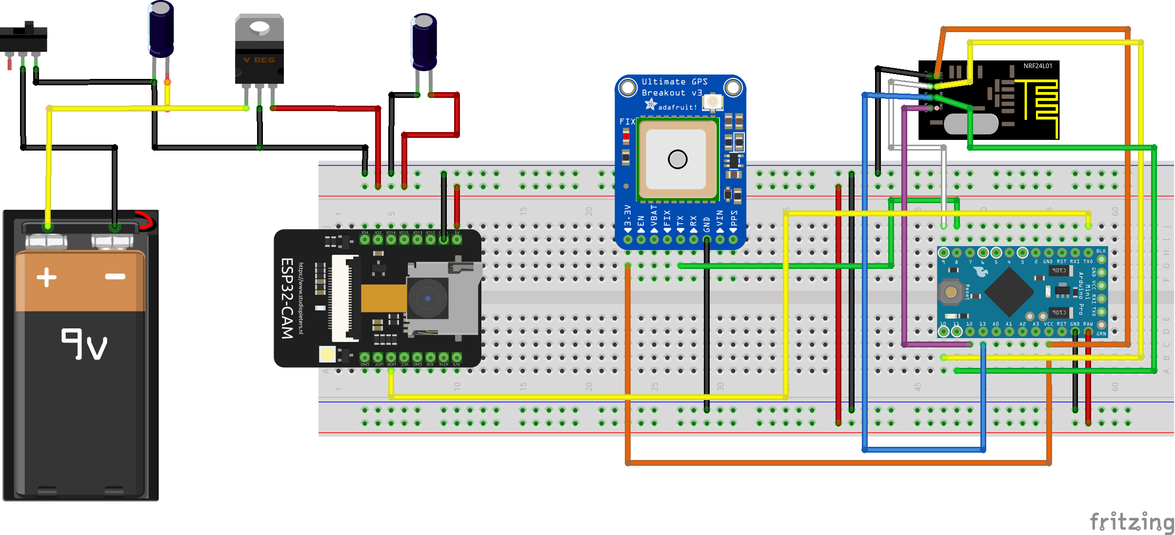
The third generation added a GPS module. Doing so allowed RF readings to be plotted in a geospatial domain. One of the biggest challenges in this design was the power distribution. Initially all power on the 3.3 V bus was provided by the ESP32-Cam module. That power configuration overloaded the 3.3 V regulator on the ESP32-Cam module, causing it to fail. The final power distribution provided 5 V separately to the ESP32-Cam module and the Arduino pro mini. Wi-Fi scanning was also introduced in this build.
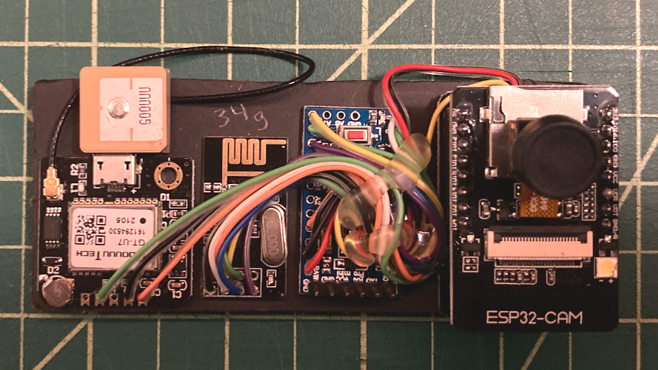
Here is a photo of the build which uses the ESP32-Cam module USB board instead of regulated battery source. As seen on the photo, the device is only 34 grams.
Here is the microcontroller code used on the Arduino Pro Mini for the GPS added configuration.
/**

Arduino_ProMini_NRF24L01-GPS-64bit-Ver1
Pro Mini Controller that monitors the following devices
NRF24L01 for 2.4 Ghz spectrum readings
GT-U7 GPS module vai software serial port
All readings are streamed out

Aug 27th, 2023 - 13:30

**/


// Libraries
#include <TinyGPS++.h>
#include <SoftwareSerial.h>
SoftwareSerial SecondSerial(8, 7); // RX, TX
#include <SPI.h>


// Variables and Constants

// Set these based on your needs
// GPS Home, https://www.google.com/maps
static const double SixtyAcres_LAT = 47.702875, SixtyAcres_LON = -122.137535;


TinyGPSPlus gps;    // The TinyGPS++ object
unsigned long last = 0UL;    // For stats that happen every 5 seconds
int PadSeconds;
int PadMinutes;
int PadDays;
int PadMonths;
float OnboardSeconds;

unsigned long serialdelay = 0; // Time counter for timed GPS checks
unsigned long delaytime = 17000; // Time of delay to allow ESP32-Cam functions to run ( Wifi Scan 12 sec ) and ( Photo 5 sec )

// Increased define CHANNELS from 64 to 256 in attempt to increase resolution

// Poor Man's Wireless 2.4GHz Scanner
//
// uses an nRF24L01p connected to an Arduino
//
// Cables are:
//     SS       -> 10   Chip Select Not - This is held to VCC to turn on chip, GPIO is not needed
//     MOSI     -> 11   Master Out Slave In - Now called PICO
//     MISO     -> 12   Master In Slave Out - Now called POCI
//     SCK      -> 13   Clock Signal
//
//     GND and VCC sould have a 10uf capacitor between them
//
// and CE       ->  9   Chip Enable - This is needed because SPI requires 2 way comms
//
// created March 2011 by Rolf Henkel
// https://forum.arduino.cc/t/poor-mans-2-4-ghz-scanner/54846
//

#define CE  9  // Chip Enable - This is needed because SPI requires 2 way comms

unsigned long myTime;

// Array to hold Channel data (32 = 1 sec, 64 = 2 sec, 128 = 4 sec, 256 = 8 sec, etc)
#define CHANNELS  128
int channel[CHANNELS];

// greyscale mapping
int  line;
char grey[] = "0123456789";
// char grey[] = " .:-=+*aRW";

// nRF24L01P registers we need
#define _NRF24_CONFIG      0x00
#define _NRF24_EN_AA       0x01
#define _NRF24_RF_CH       0x05
#define _NRF24_RF_SETUP    0x06
#define _NRF24_RPD         0x09

// get the value of a nRF24L01p register
byte getRegister(byte r)
{
  byte c;

  PORTB &=~_BV(2);
  c = SPI.transfer(r&0x1F);
  c = SPI.transfer(0);
  PORTB |= _BV(2);

  return(c);
}

// set the value of a nRF24L01p register
void setRegister(byte r, byte v)
{
  PORTB &=~_BV(2);
  SPI.transfer((r&0x1F)|0x20);
  SPI.transfer(v);
  PORTB |= _BV(2);
}

// power up the nRF24L01p chip
void powerUp(void)
{
  setRegister(_NRF24_CONFIG,getRegister(_NRF24_CONFIG)|0x02);
  delayMicroseconds(130);
}

// switch nRF24L01p off
void powerDown(void)
{
  setRegister(_NRF24_CONFIG,getRegister(_NRF24_CONFIG)&~0x02);
}

// enable RX
void enable(void)
{
    PORTB |= _BV(1);
}

// disable RX
void disable(void)
{
    PORTB &=~_BV(1);
}

// setup RX-Mode of nRF24L01p
void setRX(void)
{
  setRegister(_NRF24_CONFIG,getRegister(_NRF24_CONFIG)|0x01);
  enable();
  // this is slightly shorter than
  // the recommended delay of 130 usec
  // - but it works for me and speeds things up a little...
  delayMicroseconds(100);
}

// scanning all channels in the 2.4GHz band
void scanChannels(void)
{

  disable();
  for( int j=0 ; j<200  ; j++)
  {
    for( int i=0 ; i<CHANNELS ; i++)
    {
      // select a new channel
      setRegister(_NRF24_RF_CH,(64*i)/CHANNELS);

      // switch on RX
      setRX();

      // wait enough for RX-things to settle
      delayMicroseconds(40);

      // this is actually the point where the RPD-flag
      // is set, when CE goes low
      disable();

      // read out RPD flag; set to 1 if
      // received power > -64dBm
      if( getRegister(_NRF24_RPD)>0 )   channel[i]++;
    }
  }
}

// outputs channel data as a simple grey map
void outputChannels(void)
{
  int norm = 0;

  // find the maximal count in channel array
  for( int i=0 ; i<CHANNELS ; i++)
    if( channel[i]>norm ) norm = channel[i];

  // now output the data
  for( int i=0 ; i<CHANNELS ; i++)
  {
    int pos;

    // calculate grey value position
    if( norm!=0 ) pos = (channel[i]*10)/norm;
    else          pos = 0;

    // boost low values
    if( pos==0 && channel[i]>0 ) pos++;

    // clamp large values
    if( pos>9 ) pos = 9;

    // print it out
    Serial.print(grey[pos]);
    Serial.print(',');
    channel[i] = 0;
  }

  // indicate overall power
  Serial.print(norm);
  Serial.print(',');
  myTime = millis();
  Serial.print(myTime);
  Serial.print(',');


}


// Printout Millis Timestamp
void PrintOutMillis()
{
    // OnboardSeconds = millis();
    // OnboardSeconds = OnboardSeconds/1000;
    // Serial.print(OnboardSeconds, 3);
    myTime = millis();
    Serial.print(myTime);
    Serial.print(",");
}


// Printout Location Routine
void PrintOutLocation()
{
    String StringLat = String(gps.location.lat(), 6);
    String StringLong = String(gps.location.lng(), 6);
    String Location = String(StringLat + "," + StringLong + ",");
    Serial.print(Location);
}


// Printout Date Routine
void PrintOutDate()
{
    PadMonths = gps.date.month();
      if (PadMonths < 10)
        {
         Serial.print("0");
        }
    String StringMonth = String(gps.date.month());
    Serial.print(StringMonth);
    Serial.print("/");
    PadDays = gps.date.day();
      if (PadDays < 10)
        {
         Serial.print("0");
        }
    String StringDay = String(gps.date.day());
    Serial.print(StringDay);
    Serial.print("/");
    String StringYear = String(gps.date.year());
    Serial.print(StringYear);
    Serial.print(",");
}


// Printout Time Routine
void PrintOutTime()
{
    String StringHour = String(gps.time.hour());
    Serial.print(StringHour);
    Serial.print(":");
    PadMinutes = gps.time.minute();
      if (PadMinutes < 10)
        {
         Serial.print("0");
        }
    String StringMinutes = String(gps.time.minute());
    Serial.print(StringMinutes);
    Serial.print(":");
    PadSeconds = gps.time.second();
      if (PadSeconds < 10)
        {
         Serial.print("0");
        }
    String StringSeconds = String(gps.time.second());
    Serial.print(StringSeconds);
    Serial.print(",");
}


// Printout Speed Routine
void PrintOutSpeed()
{
    String StringMph = String(gps.speed.mph());
    Serial.print(StringMph);
    Serial.print(",");
}


// Printout Course Routine
void PrintOutCourse()
{
    String StringCourse = String(gps.course.deg());
    Serial.print(StringCourse);
    Serial.print(",");
}


// Printout Altitude Routine
void PrintOutAltitude()
{
    String StringAltitude = String(gps.altitude.feet());
    Serial.print(StringAltitude);
    Serial.print(",");
}


// Reference Bearing Routine
void BearingReference()
{

      double distanceToSixtyAcres =
        TinyGPSPlus::distanceBetween(
          gps.location.lat(),
          gps.location.lng(),
          SixtyAcres_LAT,
          SixtyAcres_LON);
      double courseToSixtyAcres =
        TinyGPSPlus::courseTo(
          gps.location.lat(),
          gps.location.lng(),
          SixtyAcres_LAT,
          SixtyAcres_LON);

      String StringDistToHome = String(distanceToSixtyAcres/1609, 6);
      Serial.print(StringDistToHome);
      Serial.print(",");
      String StringCourseToHome = String(courseToSixtyAcres, 6);
      Serial.print(StringCourseToHome);
      Serial.print(",");
      String StringCardinal = String(TinyGPSPlus::cardinal(courseToSixtyAcres));
      Serial.print(StringCardinal);
      Serial.print(',');
}


// End of serial message
void SerialMessageEnd()
{

    Serial.print("^");  // Break Character for end of serial data message

}


// This custom version of delay() ensures that the gps object
// is being "fed".
// source https://forum.arduino.cc/t/tinygps-dont-run-the-sketch-until-gps-is-fixed/1053105
void gpsLock()
{

  // Keep waiting until the fix is valid
  while( !gps.location.isValid() )
  {

    unsigned long start = millis();
    do
      {
        while (SecondSerial.available())
        gps.encode(SecondSerial.read());
      }

    while (millis() - start < 1000);

    // if (millis() > 5000 && gps.charsProcessed() < 10)
    // Serial.println(F("No GPS data received: check wiring"));


  }

}


// give ESP-32 Cam module time to complete its functions before providing serial readings
void ESP32CamWait()
{

  serialdelay = millis();
  while (millis() - serialdelay < delaytime) {
    // I'm not waiting on a lady, I'm just waiting on a friend - https://www.youtube.com/watch?v=MKLVmBOOqVU
  }

}


// Printout Global Results Routine
void PrintOutGlobalReadings()
{
    PrintOutMillis ();
    PrintOutLocation();
    PrintOutDate();
    PrintOutTime();
    PrintOutSpeed();
    PrintOutCourse();
    PrintOutAltitude();
    BearingReference();
    SerialMessageEnd();
}


void setup()
{
  Serial.begin(57600);

  SecondSerial.begin(9600);
  delay(1000);  // give GPS time to settle

  // Setup SPI
  SPI.begin();
  // Clock Speed, Bit Order, and Data Mode
  SPI.beginTransaction(SPISettings(20000000, MSBFIRST, SPI_MODE0));

  // Activate Chip Enable
  pinMode(CE,OUTPUT);
  disable();

  // now start receiver
  powerUp();

  // switch off Shockburst
  setRegister(_NRF24_EN_AA,0x0);

  // make sure RF-section is set properly
  // - just write default value...
  setRegister(_NRF24_RF_SETUP,0x0F);

  // reset line counter
  line = 0;
}

void loop()
{

  // wait for gps to get a valid lock
  gpsLock();

  // do the scan with nrf24l01
  scanChannels();

  // output the results from nrf24l01
  outputChannels();

  // monitor for serial data from gps
  // InboundSerialData();

  // output the results from gps
  PrintOutGlobalReadings();

  // give ESP-32 Cam module time to complete its functions before providing serial readings
  ESP32CamWait();

}
Here is the microcontroller code used on the ESP32-Cam module.
/*********
  Rui Santos
  Complete project details at https://RandomNerdTutorials.com/esp32-cam-take-photo-save-microsd-card

  IMPORTANT!!!
   - Select Board "AI Thinker ESP32-CAM"
   - GPIO 0 must be connected to GND to upload a sketch
   - After connecting GPIO 0 to GND, press the ESP32-CAM on-board RESET button to put your board in flashing mode

  Permission is hereby granted, free of charge, to any person obtaining a copy
  of this software and associated documentation files.
  The above copyright notice and this permission notice shall be included in all
  copies or substantial portions of the Software.

*********/

#include "WiFi.h"
#include "esp_camera.h"
#include "FS.h"                // SD Card ESP32
#include "SD_MMC.h"            // SD Card ESP32
const char* NRFReadings = "/NRF-GPS-Wifi_Readings.csv";


// Pin definition for CAMERA_MODEL_AI_THINKER
#define PWDN_GPIO_NUM     32
#define RESET_GPIO_NUM    -1
#define XCLK_GPIO_NUM      0
#define SIOD_GPIO_NUM     26
#define SIOC_GPIO_NUM     27
#define Y9_GPIO_NUM       35
#define Y8_GPIO_NUM       34
#define Y7_GPIO_NUM       39
#define Y6_GPIO_NUM       36
#define Y5_GPIO_NUM       21
#define Y4_GPIO_NUM       19
#define Y3_GPIO_NUM       18
#define Y2_GPIO_NUM        5
#define VSYNC_GPIO_NUM    25
#define HREF_GPIO_NUM     23
#define PCLK_GPIO_NUM     22

unsigned long pictureNumber = 0;
unsigned long photodelay = 0; // Time counter for timed photos
unsigned long delaytime = 5000; // Time of delay between each photo


void HardwareSetup()
{
  // Note the format for setting a serial port is as follows:
  // Serial.begin(baud-rate, protocol, RX pin, TX pin);
  // initialize serial:
  Serial.begin(57600);

  WiFi.mode(WIFI_STA);
  WiFi.disconnect();
  delay(100);

}


void StartupCamera() {

  camera_config_t config;
  config.ledc_channel = LEDC_CHANNEL_0;
  config.ledc_timer = LEDC_TIMER_0;
  config.pin_d0 = Y2_GPIO_NUM;
  config.pin_d1 = Y3_GPIO_NUM;
  config.pin_d2 = Y4_GPIO_NUM;
  config.pin_d3 = Y5_GPIO_NUM;
  config.pin_d4 = Y6_GPIO_NUM;
  config.pin_d5 = Y7_GPIO_NUM;
  config.pin_d6 = Y8_GPIO_NUM;
  config.pin_d7 = Y9_GPIO_NUM;
  config.pin_xclk = XCLK_GPIO_NUM;
  config.pin_pclk = PCLK_GPIO_NUM;
  config.pin_vsync = VSYNC_GPIO_NUM;
  config.pin_href = HREF_GPIO_NUM;
  config.pin_sscb_sda = SIOD_GPIO_NUM;
  config.pin_sscb_scl = SIOC_GPIO_NUM;
  config.pin_pwdn = PWDN_GPIO_NUM;
  config.pin_reset = RESET_GPIO_NUM;
  config.xclk_freq_hz = 20000000;
  config.pixel_format = PIXFORMAT_JPEG;  //YUV422,GRAYSCALE,RGB565,JPEG
  config.frame_size = FRAMESIZE_UXGA; // FRAMESIZE_ + QVGA (320 x 240) | CIF (352 x 288) |VGA (640 x 480) | SVGA (800 x 600) |XGA (1024 x 768) |SXGA (1280 x 1024) |UXGA (1600 x 1200)
  config.jpeg_quality = 10; // 10-63 lower number means higher quality
  config.fb_count = 1;

  // Init Camera
  esp_err_t err = esp_camera_init(&config);
  if (err != ESP_OK) {
    return;
  }

  sensor_t * s = esp_camera_sensor_get();
  s->set_whitebal(s, 0);       // 0 = disable , 1 = enable
  s->set_awb_gain(s, 0);       // 0 = disable , 1 = enable

}


void StartupMicroSD() {

  if(!SD_MMC.begin()){
    return;
  }

  uint8_t cardType = SD_MMC.cardType();
  if(cardType == CARD_NONE){
    return;
  }

}


//Append to the end of file in SD card
void appendFile(fs::FS &fs, const char * path, const char * message){

    File file = fs.open(path, FILE_APPEND);
    if(!file){
        return;
    }
    if(file.print(message)){
    } else {
    }
}


void CaptureImage() {

  camera_fb_t * fb = NULL;

  // Take Picture with Camera
  fb = esp_camera_fb_get();
  if(!fb) {
    return;
  }

  // Construct a filename that looks like "/photo_0000000001.jpg"
  pictureNumber = millis();
  String filename = "/photo_";
  if(pictureNumber < 1000000000) filename += "0";
  if(pictureNumber < 100000000) filename += "0";
  if(pictureNumber < 10000000) filename += "0";
  if(pictureNumber < 1000000) filename += "0";
  if(pictureNumber < 100000) filename += "0";
  if(pictureNumber < 10000) filename += "0";
  if(pictureNumber < 1000) filename += "0";
  if(pictureNumber < 100) filename += "0";
  if(pictureNumber < 10) filename += "0";
  filename += pictureNumber;
  filename += ".jpg";
  // Path where new picture will be saved in SD Card
  String imagefile = String(filename);

  fs::FS &fs = SD_MMC;

  File file = fs.open(imagefile.c_str(), FILE_WRITE);
  file.write(fb->buf, fb->len); // payload (image), payload length
  // file.close();
  esp_camera_fb_return(fb);


}


void ScanWifiNetworks()
{

      // WiFi.scanNetworks will return the number of networks found.
    int IntWifiNetworks = WiFi.scanNetworks();


    if (IntWifiNetworks == 0) {
    }

    else {

        String MillisString = String(millis());         // read string until meet newline character
        appendFile(SD_MMC, NRFReadings, MillisString.c_str());
        appendFile(SD_MMC, NRFReadings, ",");

        String StringWifiNetworks = String(IntWifiNetworks);         // read string until meet newline character
        appendFile(SD_MMC, NRFReadings, StringWifiNetworks.c_str());
        appendFile(SD_MMC, NRFReadings, ",");

        for (int NetworkCount = 0; NetworkCount < IntWifiNetworks; ++NetworkCount)
           {

            String StringSSID = String(WiFi.SSID(NetworkCount));
            appendFile(SD_MMC, NRFReadings, StringSSID.c_str());
            appendFile(SD_MMC, NRFReadings, ",");

            String StringRSSI = String(WiFi.RSSI(NetworkCount));
            appendFile(SD_MMC, NRFReadings, StringRSSI.c_str());
            appendFile(SD_MMC, NRFReadings, ",");

            String StringBSSIDstr = String(WiFi.BSSIDstr(NetworkCount));
            appendFile(SD_MMC, NRFReadings, StringBSSIDstr.c_str());
            appendFile(SD_MMC, NRFReadings, ",");


            String StringChannel = String(WiFi.channel(NetworkCount));
            appendFile(SD_MMC, NRFReadings, StringChannel.c_str());
            appendFile(SD_MMC, NRFReadings, ",");

            printEncryptionType(WiFi.encryptionType(NetworkCount));
            appendFile(SD_MMC, NRFReadings, ",");
           }
       }

      // Delete the scan result to free memory for code below.
      WiFi.scanDelete();


}


void printEncryptionType(int thisType) {

  // read the encryption type and print out the name:
  switch (thisType) {
            case WIFI_AUTH_OPEN:
                appendFile(SD_MMC, NRFReadings, "open");
                break;
            case WIFI_AUTH_WEP:
                appendFile(SD_MMC, NRFReadings, "WEP");
                break;
            case WIFI_AUTH_WPA_PSK:
                appendFile(SD_MMC, NRFReadings, "WPA");
                break;
            case WIFI_AUTH_WPA2_PSK:
                appendFile(SD_MMC, NRFReadings, "WPA2");
                break;
            case WIFI_AUTH_WPA_WPA2_PSK:
                appendFile(SD_MMC, NRFReadings, "WPA+WPA2");
                break;
            case WIFI_AUTH_WPA2_ENTERPRISE:
                appendFile(SD_MMC, NRFReadings, "WPA2-EAP");
                break;
            case WIFI_AUTH_WPA3_PSK:
                appendFile(SD_MMC, NRFReadings, "WPA3");
                break;
            case WIFI_AUTH_WPA2_WPA3_PSK:
                appendFile(SD_MMC, NRFReadings, "WPA2+WPA3");
                break;
            case WIFI_AUTH_WAPI_PSK:
                appendFile(SD_MMC, NRFReadings, "WAPI");
                break;
            default:
                appendFile(SD_MMC, NRFReadings, "unknown");
  }
}


void setup() {

  StartupCamera();
  StartupMicroSD();
  HardwareSetup();

  // Let things settle before logging
  delay(1000);

}


void loop() {

  // Wait for serial data input, then perform internal functions
  if(Serial.available())                                   // if there is data comming
  {
    String inputString = Serial.readStringUntil('^');         // read string until meet newline character
    appendFile(SD_MMC, NRFReadings, inputString.c_str());

    // This can take 12 seconds to complete
    ScanWifiNetworks();
    appendFile(SD_MMC, NRFReadings, "\n");

    // This can take 5 seconds to complete
    CaptureImage();

  }


}

/*
  Some Notes


*/
Field tests were inconclusive as to what RF was being detected by the NRF module in relation with the ESP32-Cam Wi-Fi scan. A fourth generation scanner was hastily made. The purpose of this scanner was to focus RF reception with a directional antenna. An arbitrary can was used and the NRF module was placed inside the can. This configuration did not include a GPS module, but did include a Compass sensor. in addition to the scanner modules, a ESP32-Cam module was used separately to photograph where the antenna was pointing with each reading. It was discovered later on that the Compass module had a fault, and the bearing would have to be provided by the photos. This configuration did not include Wi-Fi scanning.
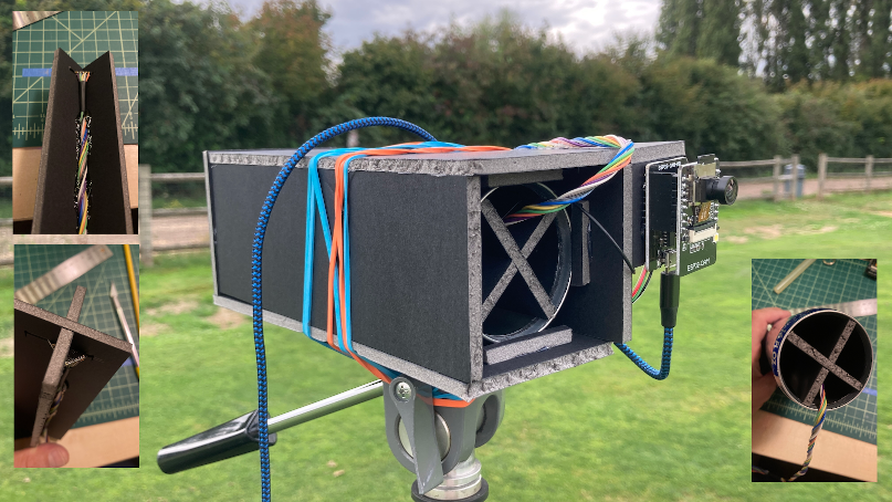
Readings from the directional antenna were limited to RF in close proximity. This range limitation was noted by others, see https://hallard.me/nrf24l01-real-life-range-test/. The less likely cause of this is from the antenna dimensions not being at center frequency. Additional attempts were made to detect the radio frequency source however there were no bearing readings to cross reference.
One possible design consideration would be a tuned antenna in a polar array. The polar array would consist of at least four quadrants as well as a device to provide bearing. The quadrants would spread out like petals from a flower. If an RF source was from a given direction, the pedals closest in that direction would indicate a higher reading. This device would operate best from a higher altitude with line of sight to the RF source. This presents a challenge because the aircraft would need to be equipped with a radio that operates outside of the frequency being surveyed.
The effectiveness of RF scanning to locate a source is highly dependent on some known limitations. FCC regulations dictate how much power a standard Wi-Fi transmitter can operate at. The NRF module has a set sensitivity, which is documented in its data sheet. Power loss from a radio signal follows an inverse square constant. See this link for more information, https://helpfulcolin.com/radio-wave-power-and-how-it-gets-reduced-by-distance/. Knowing the maximum transmit power and the sensitivity limit, the inverse power constant can be applied to determine how far the NRF will receive a signal. Do keep in mind that these are ideal conditions with outside factors not considered.
The other challenge is building a wave guide that is small enough to fit on a model RC aircraft, but efficient enough to propagate the Wi-Fi frequency. Based on the wavelenght of 2.4Ghz RF (2.4 Ghz RF λ = 12.4913524166667 cm), the parabola would be roughly 5 inches or 12.5 cm across. This means the array would likely be 1 foot across. Keeping the array thin enough so it reamains aerodynamic will result in a narrow horizontal beam. So this device has many hurdles to overcome in order to provide an accurate location. Using multiple devices to triagulate adds a whole level of complexity well outside to scope of this post.